


178 SMV 3000 Transmitter User’s Manual 1/99
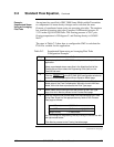
C.2 Standard Flow Equation, Continued
Table C-1 Air Through a Venturi Meter Configuration Example,
continued
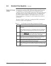
Step Action
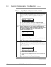
6
Enter the relevant flow process data from the Venturi Sizing Data
Sheet into the appropriate entry fields on the Process Data page as
follows:
Normal Flowrate = 630 CFM
Normal DP = 49 inches H
2
O @ 39.2 °F
Design Pressure = 129.7 psia
Design Temperature = 100°F
Standard Density = 0.0764 lbs/ft
3
Compensation Mode = Full
You can change the engineering units by clicking on the text box with
the right mouse button.
Click Next to proceed to the Flowing Variables page.
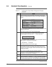
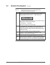
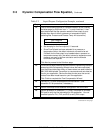
7
Click the following options for failsafe indication on the Flowing
Variables page (so that there is an “
a “ in each check box):
a Abs. Pressure
a Process Temp
This will ensure that the PV4 flow output will go to failsafe if either the
static pressure or temperature sensors fail.
• Set Damping = 1.0 seconds.
Click Next to proceed to the Solutions page.
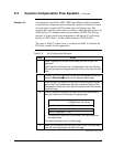
8
The calculated Kuser value appears on the Solutions page of the
Kuser Model along with a list of items (with values) that you have
configured from previous pages. Review the Wizard values to make
sure they are correct.
Click Finish to complete the Kuser calculation procedure.
9
Connect SCT to SMV and establish communications. (See
subsection 5.2 for procedure, if necessary.)
10
Perform Download of the database configuration file to the SMV.
11
Use the procedure in subsection 7.5, Using Transmitter to Simulate
PV Input to verify the Kuser and flow calculation for this application.
You can simulate inputs for PV1, PV2, and PV3 to verify PV4 output.
Continued on next page