


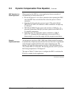

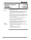


Additions to the
User Manual
The additions and changes to User Manual 34-SM-25-02 that relate to the newly
designed meter body and process heads are given in Table 1 of this addendum.
Use the information in Table 1 to reference and annotate your User Manual.
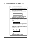
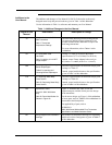
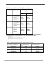
Table 1 Additions/Changes to the User Manual
Page # in User
Manual
Sub-Section Description of Change
15
3.2 Considerations for SMV
3000 Transmitter
Table 3 Transmitter
Overpressure Ratings
The Maximum Working Pressure Rating and the
Overpressure Rating has been enhanced for all
models included in this addendum except for the
draft range transmitter.
For more information, refer to Table 1 in this
Addendum.
28
4.5 Piping SMV 3000
Transmitter
Table 6 Installing ½ inch NPT
Flange Adapter
In Step 5 of Table 6, do not use the torque
specification of 47.5 to 54 N•m(35 to 40 lb-ft).
Instead, torque Flange Adapter bolts evenly to
47,5 N•m +/- 2,4 N•m (35 Lb-Ft +/- 1.8 Lb-Ft).
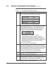
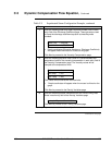
102
9.3 Inspecting and Cleaning
Barrier Diaphragms
Table 27 Inspecting and
Cleaning Barrier Diaphragms
Do not use specifications for head bolt torque given
In Step 8 of Table 27.
Instead, torque head bolts/nuts to the specifications
given in Table 2 of this addendum.
110
9.5 Replacing Meter Body
Center Section
Table 29 Replacing Meter Body
Center Section
Do not use specifications for head bolt torque given
In Step 9 of Table 29.
Instead, torque head bolts/nuts to the specifications
given in Table 2 of this addendum.
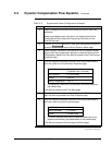
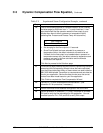
143
Replacement Parts
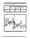
Figure 32 SMV 3000 Meter
Body
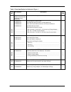
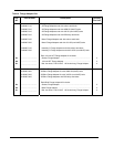
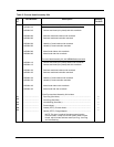
Table 38 Parts Identification for
Callouts in Figure 32
Figure 32 illustrates and Table 38 lists the
replacement part available for the previous design
of the transmitter.
For the newer design, use Figure 1 of this addendum
to locate parts, and use Table 3 of this addendum for
part numbers and descriptions.
For applicability of parts, refer to
34-SM-03-01
SMV 3000 Smart Multivariable Flow Transmitter
Specification and Model Selection Guide
147
Wiring Diagrams and Installation
Drawings
The numbers of installation drawings for transmitter
models of revision S and greater is given in Table 7
of this addendum.
2 of 8 34-SM-99-01 (Addendum to 33-SM-25-02) 03/04