


24 SMV 3000 Transmitter User’s Manual 1/99
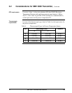
4.3 Piping SMV 3000 Transmitter
Summary
The actual piping arrangement will vary depending upon the process
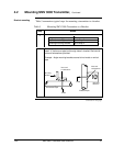
measurement requirements. Process connections can be made to standard
1/4-inch NPT female connections on 2-1/8 inch centers in the double-
ended process heads of the transmitter’s meter body. Or, the connections
in the process heads can be modified to accept 1/2 inch NPT adapter
flange for manifolds on 2, 2-1/8, or 2-1/4 inch centers
The most common type of pipe used is 1/2 inch schedule 40 steel pipe.
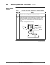
Many piping arrangements use a three-valve manifold to connect the
process piping to the transmitter. A manifold makes it easy to install and
remove a transmitter without interrupting the process. It also
accommodates the installation of blow-down valves to clear debris from
pressure lines to the transmitter.
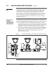
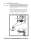
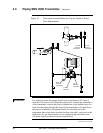
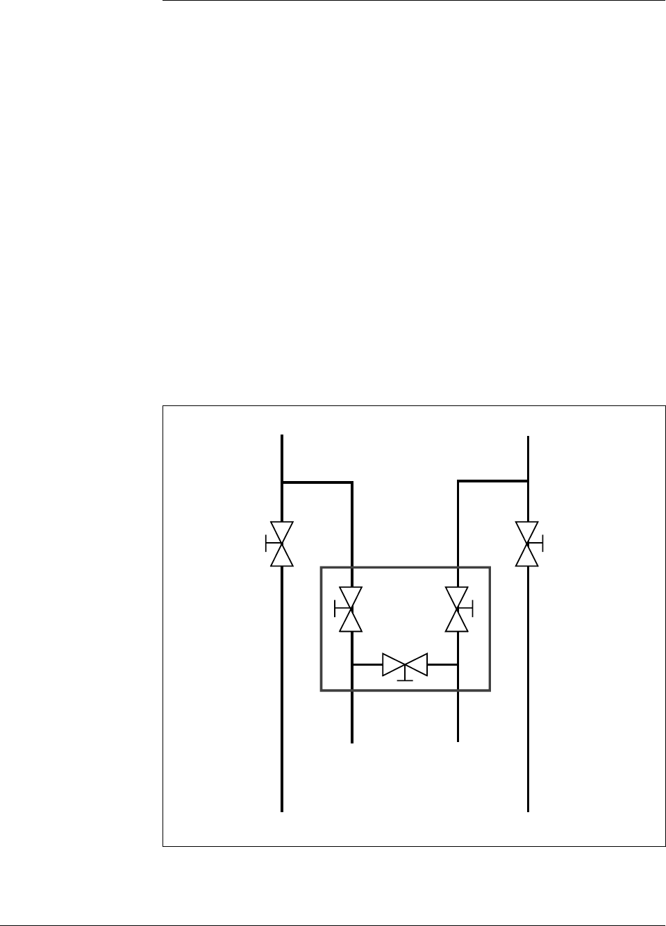
Figure 10 shows a diagram of a typical piping arrangement using a three-
valve manifold and blow-down lines for a flow measurement application.
Figure 10 Typical 3-Valve Manifold and Blow-Down Piping
Arrangement.
Blow-Down
Valve
3-Valve
Manifold
To Upstream TapTo Downstream Tap
To Low Pressure
Side of Transmitter
To High Pressure
Side of Transmitter
Blow-Down
Valve
Blow-Down
Piping
To WasteTo Waste
Blow-Down
Piping
21010
Continued on next page