


1/99 SMV 3000 Transmitter User’s Manual 31
4.5 Wiring SMV 3000 Transmitter, Continued
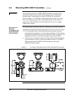
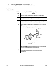
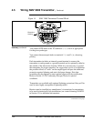
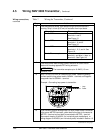
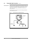
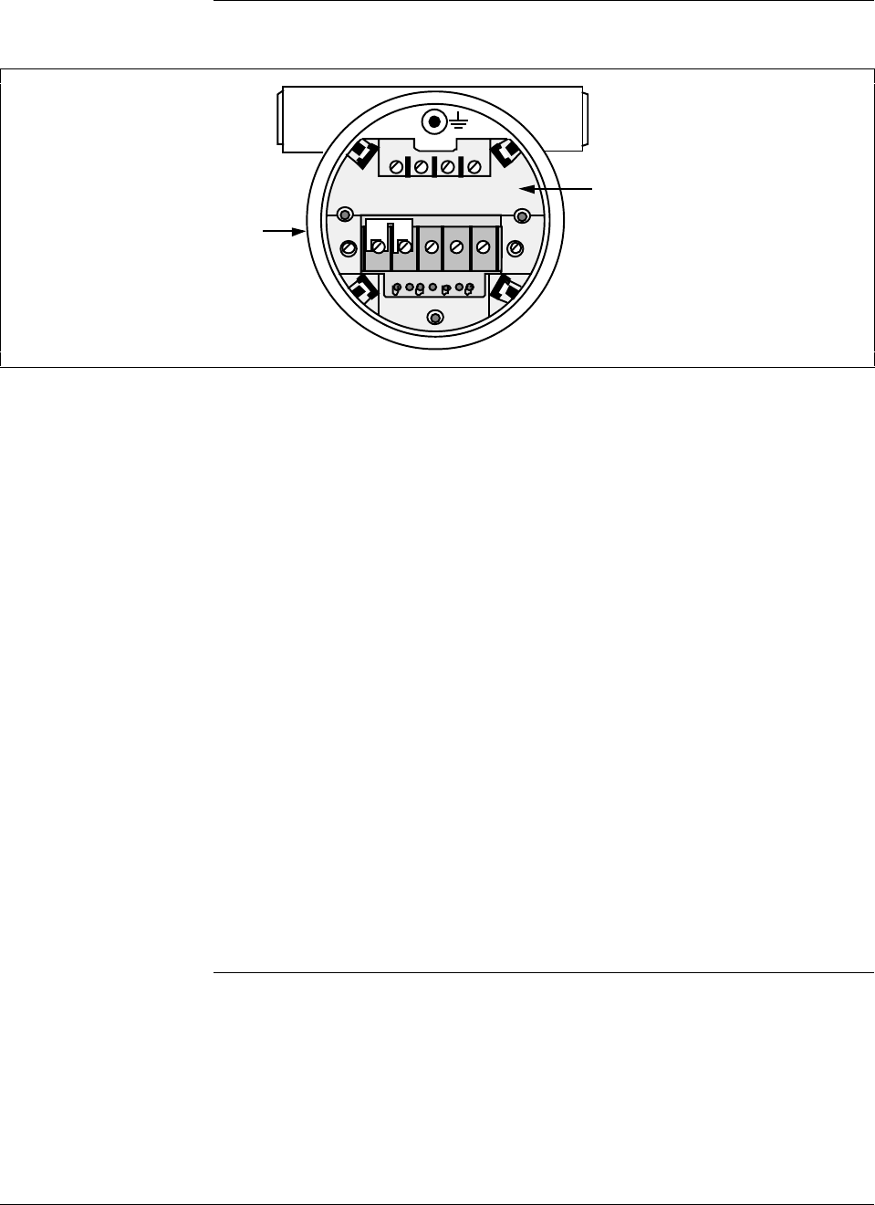
Figure 14 SMV 3000 Transmitter Terminal Block
Electronics
Housing
TEST SIG
–
+
–
+
Terminal
Block
METER L SIGNAL
12
TC
34
–––
++
Summary, continued
You connect RTD leads to the TC terminals 1, 2, 3, and 4 as appropriate
for the given probe type.
You connect thermocouple leads to terminals 1 (–) and 3 (+), observing
polarity.
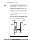
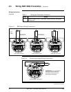
Each transmitter includes an internal ground terminal to connect the
transmitter to earth ground or a ground terminal can be optionally added to
the outside of the electronics housing. While it is not necessary to ground
the transmitter for proper operation, we suggest that you do so to minimize
the possible effects of “noise” on the output signal and provide additional
protection against lightning and static discharge damage. Note that
grounding may be required to meet optional approval body certification.
Refer to section 1.2 CE Conformity (Europe) Notice for special
conditions.
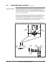
Transmitters are available with optional lightning protection if they will be
used in areas highly susceptible to lightning strikes.
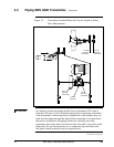
Barriers must be installed per manufacturer’s instructions for transmitters
to be used in intrinsically safe installations (see control drawing 51404251
in Section 13 for additional information).
Continued on next page