


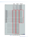
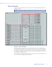

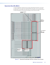
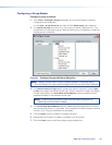
In the example in figure 46 below, Input 1 is sent to the virtual bus send by muting all eight
signals on the Input1 output mix-points. The virtual bus now serves as additional signal
processing for the input. The signal routes from virtual send A and through virtual busA
signal chain before being sent to the virtual bus return mix-point and Output 1.
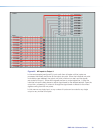
This configuration is useful when more than one input requires identical processing.
For example if all inputs were normalized but required a uniform gain to bring them up
to adequate output levels, rather than changing each pre-mix gain control by a similar
amount, all twelve inputs could be routed to a virtual bus (in this case virtual bus A). Then,
using the virtual bus A return gain control, a single adjustment can be used to apply the
same gain to all twelve inputs before sending the signal to the desired output line.
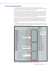
In other cases, if multiple mic inputs are being mixed with program material, only the
program material might require loudness contouring. So the mics could be routed directly
to the output but the program material input could be routed to the virtual bus return
where loudness contouring could be applied. The program material could then be routed
to the same output as the mics.
Figure 46. Input 1 to Virtual Bus A
DMP128 • Software Control 79