Level Control Blocks
To access a gain, trim or volume control to view a setting, make a change, or observe a
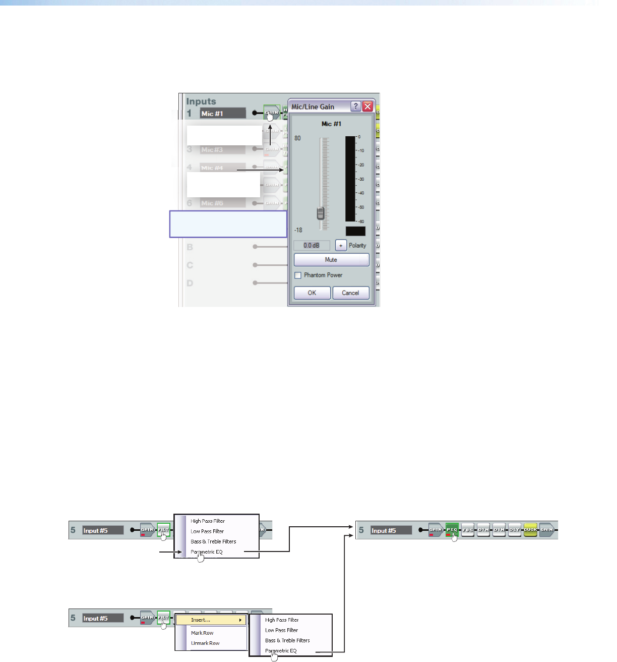
live audio meter (input gain and output volume blocks only), double-click the gain block
icon (see figure 20). This action opens a dialog box that contains the fader for that control.
A dialog box opens,
containing the full
fader control.
NOTE: In Emulate mode
(the startup mode),
the meter is not operational.
Double-click a gain,
trim, or volume control.
Figure 20. Accessing a Typical Gain Control Dialog Box
Level controls always have a fader control for setting the signal level and a digital
indication of its current setting. They can also have switches or indicators required for their
specific function.
processor Blocks
Each processor block represents a menu of one or more processors that can be inserted
into the audio stream. For blocks that provide more than one processor, only one can be
selected. Each block can be inserted by a double-click or right-click>Insert then
selecting the desired processor (see figure 21). Once a block is inserted, the selected
processor is displayed in the block and the block changes color. Processor blocks default
to bypassed. Bypass is different from mute since the processor will pass an unprocessed
signal when in bypass mode. To have them default to “not bypassed” see “Tools” on
page 86.
processor block.
Click the desired
processor.
The selected processor is displayed in the
block.
To change processor variables, double-click the
block again to open the processor dialog box.
-or-
Right-click the
processor block.
Click insert.
Click to select the
desired processor.
Figure 21. Selecting a Processor Block
DMP128 • Software Control 29


