


Front Panel Operation
DMP 128
DIGITAL MATRIX PROCESSOR
CONFIG
12345678910 11 12
CLIP
SIGNAL
INPUTS
12345678
CLIP
EXP LAN
SIGNAL
OUTPUTS
ACTIVITY
bdea Ñ Ö
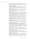
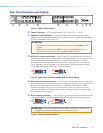
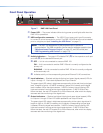
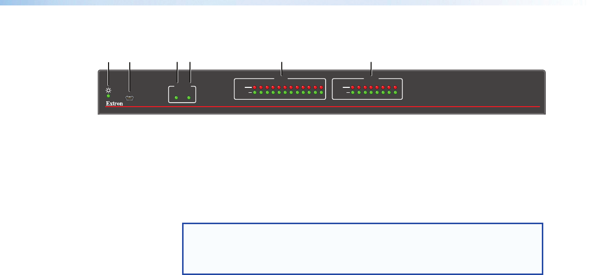
Figure 7. DMP128 Front Panel
a
Power LED — The power indicator blinks during power-up and lights solid when the
DMP128 is operational.
b
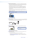
USB configuration connector — The USB 2.0 port uses a mini type-B connector
to connect to a host computer for control. The DMP128 USB driver must be installed
prior to using the port (see “Installing the USB Driver” on page17).
NOTE: The DMP128 appears as a USB peripheral with bi-directional
communication. The USB connection can be used for software operation (see
“Windows-based Program Control” on page15), and SIS control (see
“SIS Programming and Control” on page113).
c
Activity Indicators — Two green LEDs labeled EXP (
Ñ
)
for the expansion audio port
and LAN (
Ö
)
for the standard Ethernet port
Ñ
OFF — Unit is not connected to a second DMP 128.
ON — Unit is connected to another DMP128 and is currently configured as the
primary unit.
BLINKING — Unit is connected to another DMP128 and is currently configured
as the secondary unit.
Ö Indicates activity on the corresponding rear panel Ethernet RJ-45 connections.
d
Input Indicators — Stacked red (signal clipping) and green (signal present) LEDs for
inputs 1 through 12 . Each stack represents one input channel.
The green signal LED varies in brightness corresponding to the real-time input signal
level. It begins to light at – 60dBFS increasing in steps to full intensity as the signal
level increases. When the signal reaches – 3dBFS or above, the red clipping LED
lights and remains lit as long as the signal remains above – 3dBFS. When it falls
below that level, the red LED remains lit for 200 milliseconds, after which the display
resumes real-time monitoring of the signal level.
e
Output Indicators — Stacked red (signal clipping) and green (signal present) LEDs
for outputs 1 through 8. Each LED stack represents one output channel.
The green signal LED varies in brightness corresponding to the output signal level. It
begins to light at – 60dBFS increasing to full intensity corresponding to signal level
increases. When the signal level reaches – 3dBFS or above, the red clipping LED
lights and remains lit as long as the signal remains above – 3dBFS. When it falls
below that level, the red LED remains lit for 200 milliseconds, after which the display
resumes real-time monitoring of the signal level.
DMP128 • Operation 10