


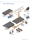
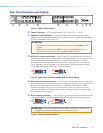
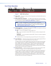
Rear Panel Features and Cabling
100-240V ~ 0.7A MAX
50/60 Hz
LAN
EXP
RS-232
Tx Rx G
RESET
MIC +48V
5678
1234
8
4 1
12345G678910G
11 12 13 14 15 G1617181920G
234
56 78
910
11 127
3
6
2
5
1
MIC/LINE INPUTS
OUTPUTS
DIGITAL I/O
REMOTE
DMP 128
ab cd ef gh ji
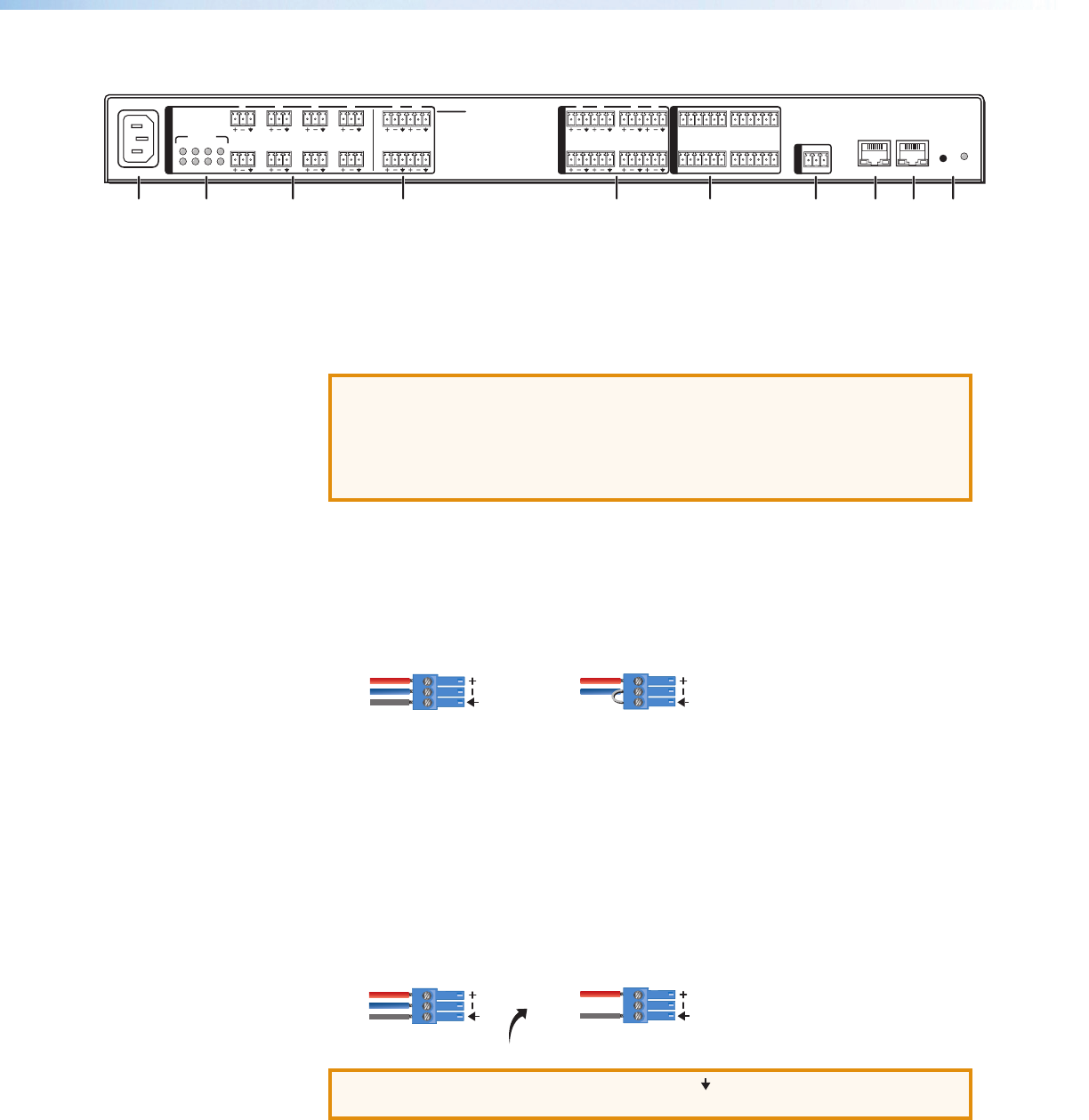
Figure 1. DMP128 Rear Panel
a Power connector — IEC power connector 100 - 240 VAC, 50 - 60 Hz
b Phantom Power indicators — Green LEDs light when +48V phantom power is
placed on the corresponding mic/line input. Phantom power voltage is not adjustable
and is only available to Micinputs 1-8.
ATTENTION:
• Condenser mics require phantom power. Dynamic mics do not require
power.
• Never set a dynamic mic to 48 V. Doing so may damage the mic. For
condenser mics, verify the mic will operate safely at 48 VDC.
c Mic/Line 1-8 input connectors — Eight 3-pole 3.5 mm captive screw connectors
accept balanced or unbalanced mono mic or line level signals. Mic/line inputs provide
gain settings to accommodate consumer (–10dBV) and professional (+ 4dBu)
operating line level sources, plus mic level sources. Up to eight mono mics or line
inputs, balanced and unbalanced in any combination may be connected to these
inputs. See the following diagram for wiring instructions.
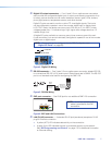
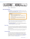
Audio Output Wiring
Audio Input Wiring
Unbalanced Output
Tip
Sleeve
NO Ground Here
Balanced Output
Tip
Sleeve
Ring
Unbalanced Input
Tip
Sleeve
Balanced Input
Tip
Sleeve
Ring
Figure 2. Balanced or Unbalanced Mic and Line Input Wiring
d Mic/Line 9-12 input connectors — Four 6-pole 3.5 mm captive screw connectors
accept balanced or unbalanced mono mic or line level signals. Mic/line inputs provide
gain settings to accommodate consumer (–10dBV) and professional (+ 4dBu)
operating line level sources, plus mic level sources. Up to four mono mics or line
inputs (or two stereo line inputs), balanced and unbalanced in any combination may
be connected to these inputs.
e Mono output connectors — Four 6-pole 3.5 mm captive screw connectors provide
up to eight balanced or unbalanced connections for mono line level output signals.
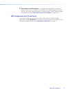
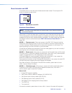
Audio Output Wiring
Audio Input Wiring
Unbalanced Output
Tip
Sleeve
NO Ground Here
Balanced Output
Tip
Sleeve
Ring
Unbalanced Input
Tip
Sleeve
Balanced Input
Tip
Sleeve
Ring
ATTENTION: Connect the sleeve to ground ( ). Connecting the sleeve only to
a negative(–) terminal will damage the audio output circuits.
Figure 3. Output Connector Wiring
DMP128 • Installation 6