


100-240V ~ 0.7A MAX
50/60 Hz
LAN
EXP
RS-232
Tx Rx G
RESET
MIC +48V
5678
1234
8
4 1
12345G678910G
11 1213 14 15 G1617181920G
234
56 78
910
11 127
3
6
2
5
1
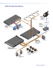
MIC/LINE INPUTS
OUTPUTS
DIGITAL I/O
REMOTE
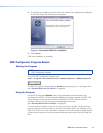
DMP 128
ab cd ef gh ji
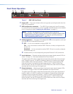
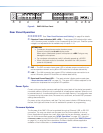
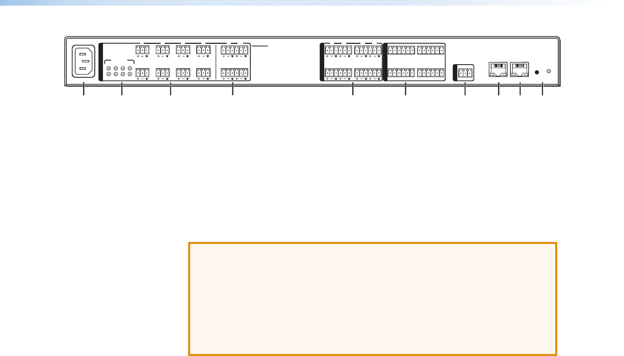
Figure 8. DMP128 Rear Panel
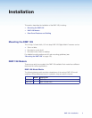
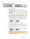
Rear Panel Operation
a c d e f g
See “Rear Panel Features and Cabling” on page 6 for details.
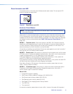
b Phantom Power indicators (MIC +48V) — These green LED indicators light when
+48 V phantom power is placed on the corresponding mic/line input. Phantom power
voltage is not adjustable and is available only on inputs 1 – 8.
ATTENTION:
• Condenser microphones require phantom power.
Dynamic microphones do not require power.
Never set an unbalanced dynamic microphone to +48V. Doing so may
damage the microphone.
• For condenser microphones, verify it will safely operate at +48 VDC.
• When a line level source is connected, be certain the +48V phantom
power is off (cleared).
h EXP — The EXP connector has a green LED to indicate proper connection to an
active expansion network and a yellow LED that blinks to indicate data activity.
i LAN — The LAN connector has a green LED to indicate proper connection to an
active LAN and a yellow LED that blinks to indicate data activity.
j Reset and Power/Reset LED — The reset actuator initiates system resets (see
“Reset Actuator and LED” on page12) . The green LED indicator adjacent to the
reset button duplicates the front panel LED operation.
Power Cycle
Current mixing and audio processor settings (the current state of the device) are saved in
nonvolatile memory. When the unit is powered off, all settings are retained. When the unit
is powered back on, it recalls settings from the nonvolatile memory. If a configuration was
in process during the power down, the saved mix, audio level, and audio DSP processor
settings become active.
On power up the unit performs a self-test. The front power indicator LED flashes during
the test, then lights solid when the unit is available for operation or programming.
Firmware Updates
The firmware of the DMP128 can be updated through an Ethernet, USB, or RS-232
connection. The user can obtain new firmware from the Extron website, or from an
Extron Applications Engineer via e-mail. After obtaining the new firmware, upload it to
the unit via the served web pages (see “HTML Operation” on page137), using the
Firmware Loader launched from the DSPConfigurator program (see “DMP Software”
on page14), or using the Extron standalone Firmware Loader software application
available on the included disc or at www.extron.com.
DMP128 • Operation 11