


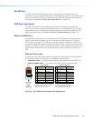
RS-232 Port
The DMP128 has a serial port that can be connected to a host device such as a
computer running the HyperTerminal utility, or the DataViewer utility. The port makes serial
control of the switcher possible. Use the protocol information listed above to make the
connection (see “Host-to-device Communications” on page116).
USB Port (front panel)
The DMP128 has a front panel USB port that can be connected to a host device
such as a computer running the HyperTerminal utility, or the DataViewer utility. The port
makes serial control of the switcher possible. Once the connection is established, SIS
programming can begin (see “Host-to-device Communications” on page116)
Ethernet (LAN) Port
The rear panel LAN connector on the device can be connected to an Ethernet LAN or
WAN. Communication between the device and the controlling device is via Telnet (a
TCP socket using port 23). The Telnet port can be changed, if necessary, via SIS. This
connection makes SIS control of the device possible using a computer connected to the
same LAN or WAN. The SIS commands and behavior of the product are identical to the
commands and behavior the product exhibits when communicating via a serial port or
USB.
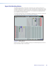
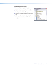
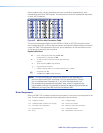
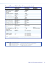
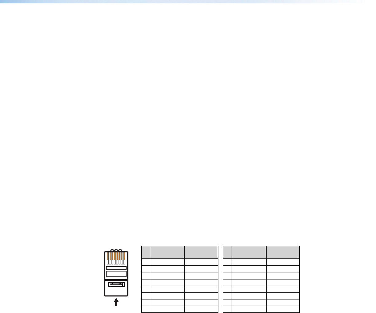
Ethernet Connection
The Ethernet cable can be terminated as a straight-through cable or a crossover cable
and must be properly terminated for your application (see figure 64).
• Crossover cable — Direct connection between the computer and the DMP128.
• Patch (straight) cable — Connection of the DMP128 to an Ethernet LAN.
A cable that is wired as T568A at one end
and T568B at the other (Tx and Rx pairs
reversed) is a "crossover" cable.
A cable wired the same at both ends is
called a "straight-through" cable, because
no pin/pair assignments are swapped.
12345678
RJ-45
Connector
Insert Twisted
Pair Wires
Pins:
Crossover Cable Straight-through Cable
Pin
1
2
3
4
5
6
7
8
Wire color
White-green
Green
White-orange
Blue
White-blue
Orange
White-brown
Brown
Wire color
T568A T568B
End 1 End 2 End 1 End 2
White-orange
Orange
White-green
Blue
White-blue
Green
White-brown
Brown
Pin
1
2
3
4
5
6
7
8
Wire color
White-green
White-orange
Blue
White-blue
White-brown
Brown
Wire color
T568BT568B
White-orange
OrangeOrange
White-green
Blue
White-blue
GreenGreen
White-brown
Brown
Figure 64. RJ-45 Ethernet Connector Pin Assignments
DMP128 • SIS Programming and Control 114