


39
GB
Other Functions
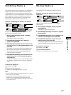
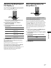
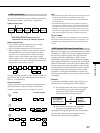
i.LINK connections
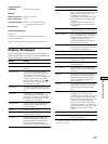
The use of i.LINK cables to connect i.LINK components as
shown below is called a “daisy chain” configuration.
i.LINK connecting cable
Data can be transmitted between any two
components even if they are indirectly connected.
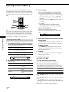
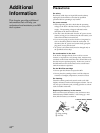
Branch connections
• Any i.LINK component with three or more i.LINK
connectors can serve as a branch point.
• Up to 63 i.LINK components can be connected in a
single configuration. However, the maximum number
of components that can be daisy-chained in a single
route is 17 (i.e., a maximum of 16 i.LINK connecting
cables in a row). Each i.LINK cable used in a single
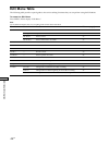
route is called a “hop.” For example, there are 6 hops in
the route between A and C in the illustration below, and
3 hops in the route between A and D.
BA
DC
Each route between A and B; A and C; A and D; B and C; B
and D; and C and D in the illustration above can have 16
hops (i.e., 17 components).
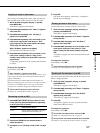
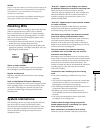
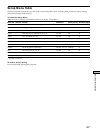
Loop-connection
A signal output from one component is transmitted to all
other components. A loop connection should thus be
avoided to prevent the return of a signal to its source.
Correct Incorrect (looped)
Notes
• Some i.LINK components (such as personal computers) do not
transfer signals when they are turned off. Refer to the
operation manual of each component to be connected before
you hook them up.
• The maximum transmission rate of an i.LINK component is
printed near its i.LINK connector. The indications S100, S200,
and S400 refer to maximum transmission rates of 100, 200, or
400 Mbps*, respectively. The actual transmission rate may be
faster or slower, depending on the differences in transmission
rates and specifications among the connected components.
z
What is Mbps?
“Mbps” is an abbreviation for megabits per second. It indicates
the amount of data transmitted per second. For example, a rate
of 200 Mbps means 200 megabits of data are transmitted in one
second.
LINC (Logical INterface Connection)
Before an audio signal can be transmitted between i.LINK
components, a “LINC” must first be established between
the receiving component (of the audio signal) and the
sending component. Establishing a “LINC” means
establishing a logical path for the transmission of digital
audio signals between the two components. Each logical
path has an ID number. Since the component that sends
an audio signal must output the signal to a path, and the
component that receives the signal must input it from the
same path, the path must be mutually known by both
components. During the establishment of a LINC, the
following communication occurs between the two i.LINK
components.
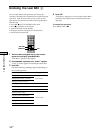
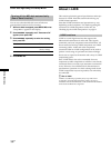
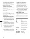
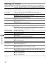
Example
A component establishing a LINC with a CD player in
order to receive an audio signal from the CD player
1 The component that will receive an audio signal
from the CD player sends a request and path
information to the CD player to establish a
transmission path for the audio signal.
1
,
2
<
2 The CD player responds to the component,
agreeing to the establishment of a LINC.
The digital audio signal transmission becomes possible
only after the communication described above has
occurred and a LINC has been established.
i.LINK
component
i.LINK
component
i.LINK
component
i.LINK
component
i.LINK
component
The component
that receives
the audio signal
CD player
(sending
component)