


24
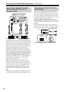
Connecting to Audio/Video Equipment—Continued
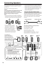
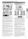
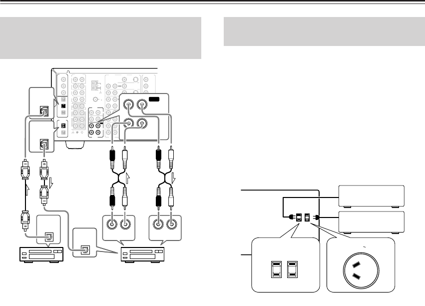
Using RCA audio connection cables, connect the output
jacks (PLAY) of the device to the TAPE AUDIO IN jacks
of the DTR-7.4 and connect the input jacks (REC) of the
device to the TAPE AUDIO OUT jacks of the DTR-7.4.
Make sure that you properly connect the left channels to
the L jacks and the right channels to the R jacks.
If the device has a digital output, connect it to either the
DIGITAL IN COAX jack or DIGITAL IN OPT jack of the
DTR-7.4, depending on the type of connector on the device.
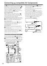
On the initial settings of the DTR-7.4, the TAPE input
source is set for digital input at the OPT 2 jack.
If the digital connection is made to a different jack, this
must be changed at Setup Menu → Input Setup →
Digital Setup (See page 36).
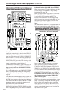
If the device has a digital input, connect it to the
DIGITAL OUT OPT jack of the DTR-7.4 for digital
recording of the REC OUT signal from the DTR-7.4.
However, if the same device also has a digital output and
it has already been connected to the DTR-7.4, you
cannot connect the digital input of the device to the
DIGITAL OUT jack of the DTR-7.4 simultaneously.
Note:
The output from the DIGITAL OUT jack of the DTR-7.4
is only the digital signal input to the DIGITAL IN jack.
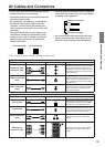
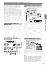
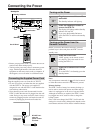
The DTR-7.4 is equipped with AC mains outlets for
connecting the power cords from other devices so that
their power is supplied through the DTR-7.4. By doing
this, you can leave the connected device turned on and
have the Standby/On button on the DTR-7.4 turn on and
off the device together with the DTR-7.4.
The shape, number, and total capacity of the AC
outlets may differ depending on the area of purchase.
Caution:
Make sure that the total capacity of the components
connected to the DTR-7.4 does not exceed the capacity
that is printed on the rear panel (e.g., TOTAL 120W).
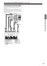
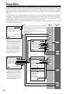
Connecting a Cassette Tape Deck,
MD Recorder, DAT Deck, or CD
Recorder (TAPE)
FM
75
OUT
OUT
OUT
OUT
L
PHONO
PRE OUT
FRONT
SUB
SURR
R
L
AUDIO
R
L
CD
TAPE
R
L
AUDIO
VIDEO
S VIDEO
MONITOR
OUT
R
L
IN
IN
IN
IN
IN
IN
IN
ZONE 2
DVD
VIDEO 1
VIDEO 2
VIDEO 3
VIDEO 4
AUDIO
AUDIO
VIDEO
S VIDEO
GND
SURR
BACK/
ZONE 2
R
L
IN
R
CENTER
R
L
MULTI CH
INPUT
FRONT
SUB
SURR
SURR
BACK
CENTER
R
L
ANTENNA
Y
P
B
PR
OUTPUT
INPUT 1
Y
P
B
PR
INPUT 2
Y
P
B
PR
DIGITAL
IN
OPT
2
1
2
3
1
3
COAX
OPT
1
2
DIGITAL
OUT
COMPONENT
VIDEO
AM
IN
RL
TAPE
OUT
1
DIGITAL
OUT
OPT
2
DIGITAL
IN
OPT
AUDIO
RL
AUDIO OUT
RL
AUDIO IN
DIGITAL
OUT
OPT
DIGITAL
IN
OPT
Cassette tape deck, MD recorder,
DAT deck, or CD recorder
MD recorder, DAT deck,
or CD recorder
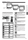
Connecting the Power Cords from
Other Devices
AC OUTLETS
AC
120
V 60
Hz
SWITCHED
TOTAL 120W 1A MAX.
AC 230
-
240
V 50
Hz
SWITCHED 100W MAX.
AC OUTLET
USA and Canadian models
Australian model