


22
Connecting to Audio/Video Equipment—Continued
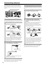
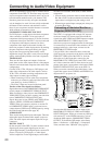
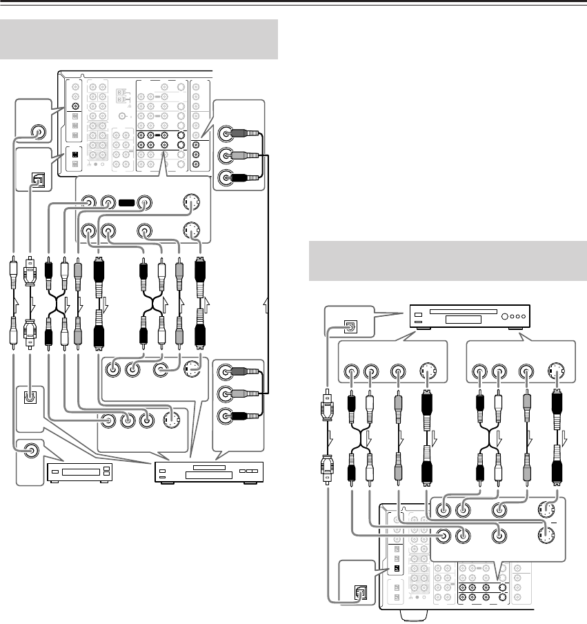
Using RCA video connection cables, connect the video
output jack (composite) of the device to the VIDEO 2
VIDEO IN jack of the DTR-7.4 and connect the video
input jack of the device to the VIDEO 2 VIDEO OUT
jack of the DTR-7.4. Or if the device has S video input
and output jacks, connect them to the VIDEO 2 S
VIDEO IN and OUT jacks of the DTR-7.4 using S video
connection cables. Or if the device has component video
outputs, connect them to one of the banks of
COMPONENT VIDEO INPUT jacks on the DTR-7.4.
On the initial settings of the DTR-7.4, the VIDEO 2
input source is set for the COMPONENT VIDEO
INPUT 2 jacks.
If you connect the device to the COMPONENT VIDEO
INPUT 1 jacks, this must be changed at Setup Menu →
Input Setup → Video Setup → Component Video (See
page 38).
Using RCA audio connection cables, connect the audio out-
put jacks of the device to the VIDEO 2 AUDIO IN jacks of
the DTR-7.4 and connect the audio input jacks of the device
to the VIDEO 2 AUDIO OUT jacks of the DTR-7.4. Make
sure that you properly connect the left channels to the L
jacks and the right channels to the R jacks.
If the device has a digital output, connect it to either the
DIGITAL IN COAX jack or DIGITAL IN OPT jack of the
DTR-7.4, depending on the type of connector on the device.
On the initial settings of the DTR-7.4, the VIDEO 2
input source is set for digital input at the COAX 3 jack.
If the digital connection is made at a different jack, this
must be changed at Setup Menu → Input Setup →
Digital Setup (See page 36).
If the device has a digital input, connect it to the DIGI-
TAL OUT OPT jack of the DTR-7.4 for digital record-
ing of the REC OUT signal from the DTR-7.4.
However, if the same device also has a digital output
and it has already been connected to the DTR-7.4, you
cannot connect the digital input of the device to the
DIGITAL OUT jack of the DTR-7.4 simultaneously.
Note:
The output from the DIGITAL OUT jack of the DTR-7.4
is only the digital signal input to the DIGITAL IN jack.
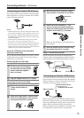
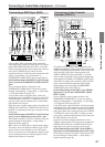
Using an RCA video connection cable, connect the
video output jack (composite) of the device to the
VIDEO 3 (or 4) VIDEO IN jack of the DTR-7.4. Or if
the device has an S video output jack, connect it to the
VIDEO 3 (or 4) S VIDEO IN jack of the DTR-7.4 using
an S video connection cable. Or if the device has compo-
nent video outputs, connect them to one of the banks of
COMPONENT VIDEO INPUT jacks on the DTR-7.4.
On the initial settings of the DTR-7.4, the VIDEO 3
and 4 input sources are set for the COMPONENT
VIDEO INPUT 2 jacks.
If you connect the device to the COMPONENT VIDEO
INPUT 1 jacks, this must be changed at Setup Menu → Input
Setup → Video Setup → Component Video (See page 38).
Using an RCA audio connection cable, connect the
audio output jack of the device to the VIDEO 3 (or 4)
AUDIO IN jacks of the DTR-7.4. Make sure that you
properly connect the left channel to the L jack and the
right channel to the R jack.
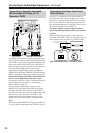
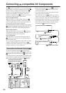
Connecting a DVD Recorder or Other
Digital Video Recording Device (VIDEO 2)
FM
75
OUT
OUT
OUT
OUT
L
PHONO
PRE OUT
FRONT
SUB
SURR
R
L
AUDIO
R
L
CD
TAPE
R
L
AUDIO
VIDEO
S VIDEO
MONITOR
OUT
R
L
IN
IN
IN
IN
IN
IN
IN
ZONE 2
DVD
VIDEO 1
VIDEO 2
VIDEO 3
VIDEO 4
AUDIO
AUDIO
VIDEO
S VIDEO
GND
SURR
BACK/
ZONE 2
R
L
IN
R
CENTER
R
L
MULTI CH
INPUT
FRONT
SUB
SURR
SURR
BACK
CENTER
R
L
ANTENNA
Y
P
B
PR
OUTPUT
INPUT 1
Y
P
B
PR
INPUT 2
Y
P
B
PR
DIGITAL
IN
OPT
2
1
2
3
1
3
COAX
OPT
1
2
DIGITAL
OUT
COMPONENT
VIDEO
AM
IN
RL
RL
VIDEO 2
AUDIO
VIDEO S VIDEO
OUT
RL
AUDIO
OUTPUT
VIDEO
OUTPUT
S VIDEO
OUTPUT
RL
AUDIO
INPUT
VIDEO
INPUT
S VIDEO
INPUT
DIGITAL
IN
COAX
3
1
DIGITAL
OUT
OPT
Y
P
B
PR
COMPONENT
VIDEO
INPUT 2
Y
P
B
PR
COMPONENT
VIDEO
OUTPUT
DIGITAL
OUT
COAX
DIGITAL
IN
OPT
Digital device
DVD recorder
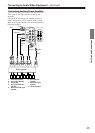
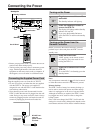
Connecting a Satellite Tuner, Televi-
sion, or Settop Box (VIDEO 3 or 4)
FM
75
OUT
OUT
OUT
OUT
L
PHONO
PRE OUT
FRONT
SUB
SURR
R
L
AUDIO
R
L
CD
TAPE
R
L
AUDIO
VIDEO
S VIDEO
MONITOR
OUT
R
L
IN
IN
IN
IN
IN
IN
IN
ZONE 2
DVD
VIDEO 1
VIDEO 2
VIDEO 3
VIDEO 4
AUDIO
AUDI O
VIDEO
S VIDEO
GND
SURR
BACK/
ZONE 2
R
L
IN
R
CENTER
R
L
MULTI CH
INPUT
FRONT
SUB
SURR
SURR
BACK
CENTER
R
L
ANTENNA
Y
P
B
PR
OUTPUT
INPUT 1
Y
P
B
PR
INPUT 2
Y
P
B
PR
DIGITAL
IN
OPT
2
1
2
3
1
3
COAX
OPT
1
2
DIGITAL
OUT
COMPONENT
VIDEO
AM
3
DIGITAL
IN
OPT
DIGITAL OUT
OPT
IN
IN
RL
VIDEO 4
VIDEO 3
AUDIO
VIDEO S VIDEO
RL
AUDIO
OUT
VIDEO
OUT
S VIDEO
OUT
RL
AUDIO
OUT
VIDEO
OUT
S VIDEO
OUT
Satellite tuner, television, or settop box