


18
Connecting Speakers
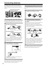
After determining the layout of your speaker system, it
is now necessary to connect the speakers correctly to
your DTR-7.4.
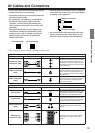
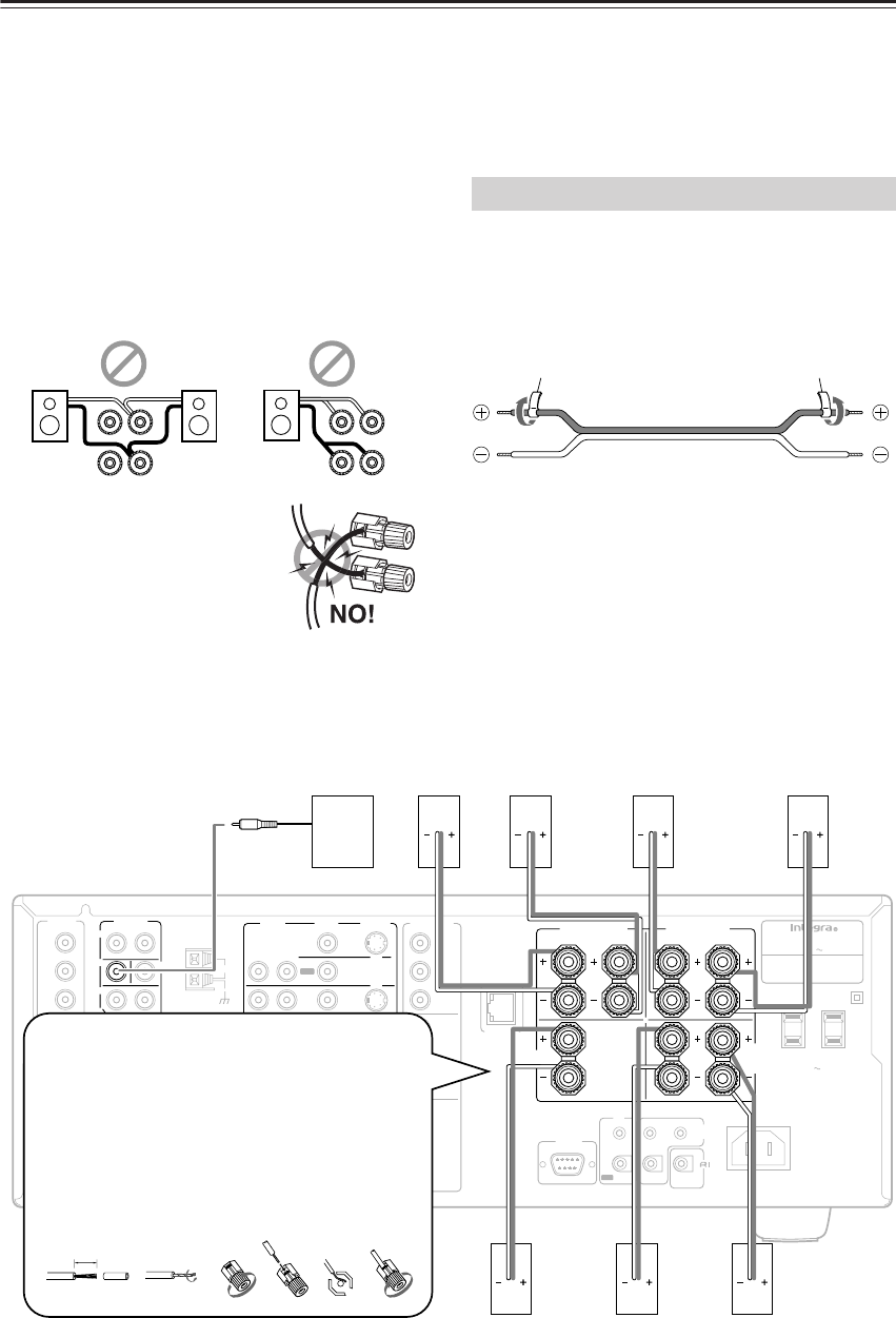
You can also use banana plugs/connectors.
Caution:
Connect only speakers with an impedance between 4 and
16 Ω to the DTR-7.4. If the impedance of even one
speaker is between 4 and 6 Ω, be sure to set the speaker
impedance setting accordingly (See page 30).
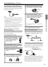
Notes:
• Even if you are using only one speaker or listening to
monaural (mono) sound, never connect a single speaker
in parallel to both the right and left-channel terminals.
• To prevent damage to circuitry,
never short-circuit the positive (+)
and negative (–) speaker wire.
• Be sure to connect the positive and
negative cables for the speakers
properly. If they are mixed up, the
left and right signals will be reversed
and the audio will sound unnatural.
• Do not connect more than one speaker cable to one
speaker terminal. Doing so may damage the DTR-7.4.
• Connect either your surround back speakers or the
speakers you will be using in the remote zone (Zone
2) to the SURR BACK/ZONE 2 SPEAKERS
terminals (See page 66).
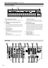
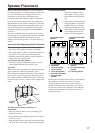
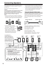
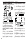
The positive speaker terminals on the DTR-7.4 are color
coded for easy identification. Attach the supplied
speaker labels to the speaker cables, and then match the
colors on the speaker cables to the corresponding
terminals.
The speaker channels are colored as follows:
Front left speaker (+): White
Front right speaker (+): Red
Center speaker (+): Green
Surround left speaker (+): Blue
Surround right speaker (+): Grey
Surround back/Zone 2 left speaker (+): Brown
Surround back/Zone 2 right speaker (+): Tan
R
L
R
L
R
L
R
L
+
–
+
–
+
–
+
–
Using the Speaker Cable Labels
Speaker cable label
Speaker cable label
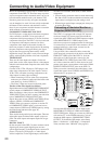
FM
75
OUT
OUT
OUT
OUT
L
PHONO
PRE OUT
FRONT
SUB
SURR
R
L
AUDIO
R
L
CD
TAPE
R
L
AUDIO
VIDEO
S VIDEO
MONITOR
OUT
R
L
IN
IN
IN
IN
IN
IN
IN
ZONE 2
DVD
VIDEO 1
VIDEO 2
VIDEO 3
VIDEO 4
AUDIO
AUDIO
VIDEO
S VIDEO
GND
SURR
BACK/
ZONE 2
R
L
IN
AC
INLET
R
CENTER
ETHERNET
(Net -Tune)
R
L
MULTICH
INPUT
FRONT
SUB
SURR
SURR
BACK
CENTER
R
L
ANTENNA
Y
P
B
PR
OUTPUT
INPUT 1
Y
P
B
PR
INPUT 2
Y
P
B
PR
SURR
BACK/
ZONE 2
SPEAKERS
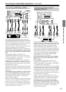
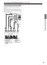
FRONT SPEAKERS
L
RL
R
SURR SPEAKERS
CENTER
SPEAKER
R
L
AC OUTLETS
AC
120
V 60
Hz
SWITCHED
TOTAL 120W 1A MAX.
IN
ZONE 2
REMOTE
CONTROL
A
B
OUT
12
V
TRIGGER OUT
DIGITAL
IN
OPT
2
1
2
3
1
3
COAX
OPT
1
2
DIGITAL
OUT
AV RECEIVER
MODEL NO. DTR
-
7.4
RATING
:
AC 120
V 60
Hz 8.1
A
COMPONENT
VIDEO
I
R
RS232
AM
25341
5/8"
(15mm)
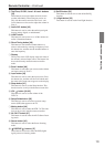
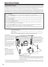
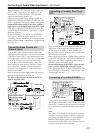
Use the PRE OUT
SUBWOOFER jack to
connect a subwoofer with a
built-in power amplifier. If
your subwoofer does not have
a built-in amplifier, connect an
amplifier to the PRE OUT
SUBWOOFER jack and the
subwoofer to the amplifier.
Subwoofer
Front
right
speaker
Front
left
speaker
Surround
right
speaker
Surround
left
speaker
Center
speaker
Surround
back
right
speaker
Surround
back left
speaker
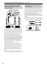
Connecting the speaker cable
1. Strip away approx. 5/8 inch (15 mm) of the
wire insulation.
2. Twist the wire ends tightly together.
3. Unscrew the speaker terminal cap.
4. Insert the exposed wire end.
5. Screw down the speaker terminal cap.