20
Connecting to Audio/Video Equipment
Here is an explanation of typical ways to connect various
components to the DTR-7.4. There are many ways that
any one component can be connected, and it is up to you
to decide which method best fits your situation. The
directions given here are only one option and should
only be thought of as such. It is best to fully understand
the nature of each connector and terminal as well as
those of your components and their features to ascertain
which method of connection is best.
COMPONENT VIDEO INPUT/OUTPUT
For DVD players or other devices that have component
video connectors, the DTR-7.4 has two banks of
component video input connectors (Y, P
B, PR) for direct
component video input. The DTR-7.4 also has one bank
of component video output connectors for direct
component video output to the matrix decoder of a
television, projector, or other display device. By sending
the pure component video signal directly, the signal
forgoes the extra processing that normally would
degrade the image. The result is vastly increased image
quality, with incredibly lifelike colors and crisp details.
VIDEO IN/OUT
These are the video inputs and outputs. On the rear
panel, there are five video inputs and two video outputs
and each one includes both composite video and S video
configurations.
Connect VCRs, VTRs, LD players, DVD players, and
other video components to the video inputs. Connect
VCRs, VTRs, and other recording components to the
video outputs to make video recordings.
• When connecting a VCR or other video component,
make sure you connect its audio and video leads to the
same bank (e.g., both to VIDEO 3).
• The Video 5 inputs are located on the front panel.
The flow of the video signals is as follows:
Signals that comes in from COMPONENT VIDEO INPUT
are only output to COMPONENT VIDEO OUTPUT.
When connecting a video player to the COMPONENT
VIDEO INPUT jacks, be sure to connect your television
to the COMPONENT VIDEO OUTPUT jacks.
Signals that come in from VIDEO and S VIDEO IN are
output to VIDEO, S VIDEO and COMPONENT
VIDEO. When you connect a projector or monitor TV
to COMPONENT VIDEO inputs, you do not have to
connect them to VIDEO and S VIDEO inputs by setting
the Video Setup Sub-menu (See page 38).
AUDIO IN/OUT
These are the analog audio inputs and outputs. There are
eight audio inputs and three audio outputs on the rear
panel. The audio inputs and outputs require RCA-type
connectors.
DIGITAL IN/OUT
On the rear panel of the DTR-7.4, there are three coaxial
digital inputs, three optical digital inputs, and two
optical digital outputs. To the digital inputs, connect CD
players, LD players, DVD players, or other digital
source components. To the digital output, connect MD
recorders, CD recorders, DAT decks, or other similar
components.
• Since an analog connection must be made when using
Rec Out or Zone 2, make sure that the connection to the
input source is not digital only, but analog as well.
• When using an optical input or output jack, always use
an optical fiber cable.
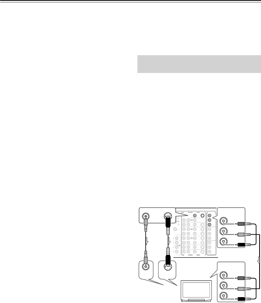
The DTR-7.4 is equipped with a simple Y/C separate
circuit and simple Y/C mixed circuit. Since both the
signals from the S VIDEO and VIDEO inputs are output
to the MONITOR OUT S VIDEO output, if the
television or projector is equipped with an S video input,
it is unnecessary to connect the video connectors. If it is
equipped with only a video input, connect it to the
MONITOR OUT VIDEO output.
Using an RCA video connection cable, connect the
video input jack (composite) of the device to the MON-
ITOR OUT VIDEO jack of the DTR-7.4. Or if the
device has an S video input jack, connect it to the
MONITOR OUT S VIDEO jack of the DTR-7.4 using
an S video connection cable. Or if the device has com-
ponent video inputs, connect them to the bank of COM-
PONENT VIDEO OUTPUT jacks on the DTR-7.4.
When you use the connections described above, video
signals that come in from S VIDEO and VIDEO IN are
output to the TV, projector, etc.
Note that the OSD Menu data will be output to the
MONITOR OUT VIDEO, S VIDEO and COMPO-
NENT VIDEO jacks. When you connect any OSD-spe-
cific monitor TV to the VIDEO connectors, you can
disable the OSD output to COMPONENT VIDEO
OUTPUT. To disable the OSD output, select Setup
Menu → Preference → OSD Setup → Component
Video, and then select “OSD Off” (See page 63).
Connecting a Television Monitor or
Projector (MONITOR OUT)
FM
75
OUT
OUT
OUT
OUT
PHONO
UDIO
L
CD
TAPE
L
AUDIO
VIDEO
S VIDEO
MONITOR
OUT
R
L
IN
IN
IN
IN
IN
IN
IN
ZONE 2
DVD
VIDEO 1
VIDEO 2
VIDEO 3
VIDEO 4
UDIO
AUDIO
VIDEO
S VIDEO
R
L
IN
T
ENNA
Y
P
B
PR
OUTPUT
INPUT 1
Y
P
B
PR
INPUT 2
Y
P
B
PR
COMPONENT
VIDEO
AM
Y
P
B
PR
VIDEO
S VIDEO
MONITOR
OUT
VIDEO
IN
S VIDEO
IN
COMPONENT
VIDEO
OUTPUT
Y
P
B
PR
COMPONENT
VIDEO
INPUT
TV,
projector,
etc.


