


11
Index Parts and Facilities—Continued
For more information regarding connection procedures,
see pages indicated in brackets [ ].
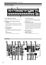
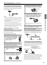
1 DIGITAL IN/OUT [21-24]
These jacks are for connecting components with
digital input and output capabilities. To connect a
CD player, see page 23; to connect an MD or CD
recorder, see page 24; to connect a DAT deck, see
page 24; to connect a DVD player, see page 21; to
connect a DVD recorder, see page 22; and to con-
nect a digital satellite tuner, see page 22.
2 PRE OUT [18, 25, 66]
To use the DTR-7.4 as a preamplifier, connect a
power amplifier to this jack.
3 ANTENNA [14]
These jacks are for connecting the FM indoor
antenna and the AM loop antenna that are supplied
with the DTR-7.4.
4 ZONE 2 OUT [66]
This jack is for connecting the component that will
be used in the remote zone (Zone 2).
5 MONITOR OUT VIDEO/S VIDEO [20]
These jacks are for connecting to the video input
jacks on television monitors or projectors.
6 COMPONENT VIDEO OUTPUT [20]
These jacks are for connecting to the component
video input jacks on television monitors or projectors.
7 ETHERNET (Net-Tune) [73]
This connector is for connecting to an Ethernet network.
8 SPEAKERS [18, 66]
These terminals are for connecting the speakers.
9 AC OUTLETS [24]
This AC outlet is provided to plug in the power cord
from another component. The shape and number of
the AC outlet depend on the shipping destination.
0 MULTI CH INPUT [64]
This connector is for connecting components with a
multichannel output.
A PHONO/CD/TAPE AUDIO IN/OUT [23, 24]
These connectors are for connecting to the audio
input and output jacks on audio components. To
connect a turntable, see page 23; to connect a CD
player, see page 23; and to connect a cassette tape
deck, MD recorder, or CD recorder, see page 24.
B DVD/VIDEO1-4 IN/OUT [21, 22]
These connectors are for connecting to the video
input and output jacks on video components. To
connect a DVD player, see page 21; to connect a
DVD recorder, see page 22; to connect a VCR, see
page 21; and to connect a digital satellite tuner, see
page 22.
C COMPONENT VIDEO INPUT1/2 [21, 22]
These connectors are for connecting to the compo-
nent video outputs of video components that have
them. To connect a DVD player, see page 21; to
connect a DVD recorder, see page 22; and to con-
nect a digital satellite tuner, see page 22.
D RS 232
This port is for connecting the DTR-7.4 to home
automation and external controllers.
E IR IN/OUT [69]
These connectors are for connecting the remote sen-
sor of a multi-room kit (sold separately).
F 12V TRIGGER OUT ZONE 2 A/B [71]
These connectors are used to connect to the 12V
TRIGGER IN terminal of a component.
G [26]
This jack is for connecting other Integra/Onkyo
components equipped with the same terminal.
The audio connection cables must also be con-
nected.
H AC INLET [27]
This connector is for connecting the supplied power
cord.
Facilities and Connections