


23
Connecting to Audio/Video Equipment—Continued
When hooking up a TV with audio outputs, make sure
the TV’s audio output setting. You might have to go
through the TV’s menu and set the TV Fixed audio
output and then internal speakers off.
If the device has a digital output, connect it to either the
DIGITAL IN COAX jack or DIGITAL IN OPT jack of the
DTR-7.4, depending on the type of connector on the device.
On the initial settings of the DTR-7.4, the VIDEO 3
input source is set for digital input at the OPT 3 jack.
If the digital connection is made at a different jack, this
must be changed at Setup Menu → Input Setup → Digital
Setup (See page 36).
On the initial settings of the DTR-7.4, the VIDEO 4
input source is not set for digital input. If you are
connecting a digital component, these settings must be
changed at Setup Menu → Input Setup → Digital Setup
(See page 36).
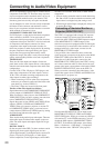
Using an RCA video connection cable, connect the
video output jack (composite) of the device to the Video
5 Video jack of the DTR-7.4. Or if the device has an S
video output jack, connect it to the Video 5 S Video jack
of the DTR-7.4 using an S video connection cable.
Using an RCA audio connection cable, connect the
audio output jack of the device to the Video 5 Audio
jacks of the DTR-7.4. Make sure that you properly
connect the left channel to the L jack and the right
channel to the R jack.
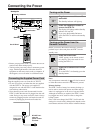
If the device has an optical digital output, connect it to
the Video 5 Digital jack of the DTR-7.4.
The Video 5 digital input is fixed to the OPTICAL
input on the front panel.
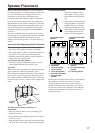
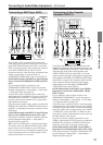
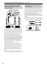
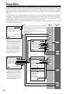
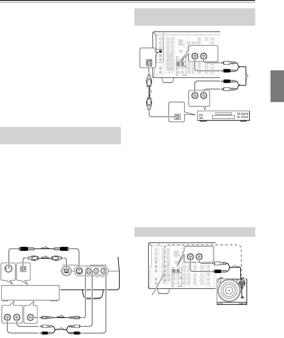
Using an RCA audio connection cable, connect the
output jacks of the compact disc player to the CD
AUDIO jacks of the DTR-7.4. Make sure that you
properly connect the left channel to the L jack and the
right channel to the R jack.
If the compact disc player has a digital output, connect it
to either the DIGITAL IN COAX jack or DIGITAL IN
OPT jack of the DTR-7.4, depending on the type of
connector on the compact disc player.
On the initial settings of the DTR-7.4, the CD input
source is set for digital input at the OPT 1 jack.
If the digital connection is made to a different jack, this
must be changed at Setup Menu → Input Setup → Dig-
ital Setup (See page 36).
.
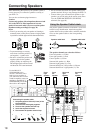
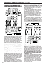
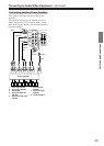
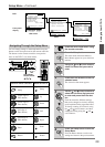
Using an RCA audio connection cable, connect the
output jacks of the turntable to the PHONO audio jacks
of the DTR-7.4. Make sure that you properly connect the
left channel to the L jack and the right channel to the R
jack.
Note:
The DTR-7.4 is designed for use with moving magnet
cartridges. For proper operation, connect a ground (or
earth) wire to the GND terminal. For some turntables,
however, connecting the ground wire may cause
increased noise, and in such a case, a ground wire is not
necessary and should not be connected.
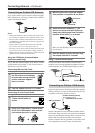
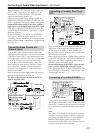
Connecting Video Camera, etc.
(Video 5 Input)
Video 5 Input
S Video
Audio
Video L R
DTR
-
7. 4
Digital
R
L
AUDIO OUT VIDEO
OUT
S VIDEO
OUT
DIGITAL
OUT
R
L
R
L
Video camera/ Video
game (Video 5 Input)
Front panel
Connecting a Compact Disc Player
(CD)
Connecting a Turntable (PHONO)
FM
75
OUT
OUT
OUT
OUT
L
PHONO
PRE OUT
FRONT
SUB
SURR
R
L
AUDIO
R
L
CD
TAPE
R
L
AUDIO
VIDEO
S VIDEO
MONITOR
OUT
R
L
IN
IN
IN
IN
IN
IN
IN
ZONE 2
DVD
VIDEO 1
VIDEO 2
VIDEO 3
VIDEO 4
AUDIO
AUDIO
VIDEO
S VIDEO
GND
SURR
BACK/
ZONE 2
R
L
IN
R
CENTER
R
L
MULTI CH
INPUT
FRONT
SUB
SURR
SURR
BACK
CENTER
R
L
ANTENNA
Y
P
B
PR
OUTPUT
INPUT 1
Y
P
B
PR
INPUT 2
Y
P
B
PR
DIGITAL
IN
OPT
2
1
2
3
1
3
COAX
OPT
1
2
DIGITAL
OUT
COMPONENT
VIDEO
AM
CD
IN
RL
1
DIGITAL
IN
OPT
DIGITAL
OUT
OPT
AUDIO
RL
AUDIO OUT
CD player
FM
75
OUT
OUT
OUT
OUT
L
PHONO
PRE OUT
FRONT
SUB
SURR
R
L
AUDIO
R
L
CD
TAPE
R
L
AUDIO
VIDEO
S VIDEO
MONITOR
OUT
R
L
IN
IN
IN
IN
IN
IN
IN
ZONE 2
DVD
VIDEO 1
VIDEO 2
VIDEO 3
VIDEO 4
AUDIO
AUDIO
VIDEO
S VIDEO
GND
SURR
BACK/
ZONE 2
R
L
IN
R
CENTER
R
L
MULTI CH
INPUT
FRONT
SUB
SURR
SURR
BACK
CENTER
R
L
ANTENNA
Y
P
B
PR
OUTPUT
INPUT 1
Y
P
B
PR
INPUT 2
Y
P
B
PR
DIGITAL
IN
OPT
2
1
2
3
1
3
COAX
OPT
1
2
DIGITAL
OUT
COMPONENT
VIDEO
AM
PHONO
IN
RL
AUDIO
Ground wire (earth)
Facilities and Connections