


Chapter 1 61
Agilent EXA Signal Analyzer
Power Suite Measurements
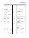
Description Specifications Supplemental Information
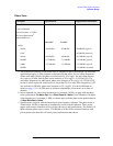
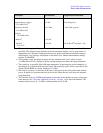
Case: Radio Std = IS-95 or J-STD-008
Method
RBW method
a
a. The RBW method measures the power in the adjacent channels within the defined resolution
bandwidth. The noise bandwidth of the RBW filter is nominally 1.055 times the 3.01 dB
bandwidth. Therefore, the RBW method will nominally read 0.23 dB higher adjacent channel
power than would a measurement using the integration bandwidth method, because the noise
bandwidth of the integration bandwidth measurement is equal to that integration bandwidth.
For cmdaOne ACPR measurements using the RBW method, the main channel is measured in
a 3 MHz RBW, which does not respond to all the power in the carrier. Therefore, the carrier
power is compensated by the expected under-response of the filter to a full width signal, of
0.15 dB. But the adjacent channel power is not compensated for the noise bandwidth effect.
The reason the adjacent channel is not compensated is subtle. The RBW method of measuring
ACPR is very similar to the preferred method of making measurements for compliance with
FCC requirements, the source of the specifications for the cdmaOne Spur Close specifica-
tions. ACPR is a spot measurement of Spur Close, and thus is best done with the RBW
method, even though the results will disagree by 0.23 dB from the measurement made with a
rectangular passband.
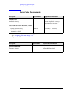
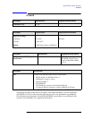
ACPR Relative Accuracy
Offsets < 750 kHz
b
Offsets > 1.98 MHz
c
b. The specified ACPR accuracy applies if the measured ACPR substantially exceeds the ana-
lyzer dynamic range at the specified offset. When this condition is not met, there are addi-
tional errors due to the addition of analyzer spectral components to UUT spectral
components. In the worst case at these offsets, the analyzer spectral components are all coher-
ent with the UUT components; in a more typical case, one third of the analyzer spectral power
will be coherent with the distortion components in the UUT. Coherent means that the phases
of the UUT distortion components and the analyzer distortion components are in a fixed rela-
tionship, and could be perfectly in-phase. This coherence is not intuitive to many users,
because the signals themselves are usually pseudo-random; nonetheless, they can be coher-
ent.
When the analyzer components are 100% coherent with the UUT components, the errors add
in a voltage sense. That error is a function of the signal (UUT ACPR) to noise (analyzer
ACPR dynamic range limitation) ratio, SN, in decibels.
The function is error = 20 × log(1 + 10
−SN/20
)
For example, if the UUT ACPR is −62 dB and the measurement floor is −82 dB, the SN is
20 dB and the error due to adding the analyzer distortion to that of the UUT is 0.83 dB.
±0.08 dB
±0.10 dB