


16 Chapter 1
Agilent EXA Signal Analyzer
Frequency and Time
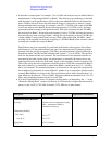
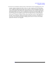
a. In the band overlap regions, for example, 3.5 to 3.6 GHz, the analyzer may use either band for
measurements, in this example Band 0 or Band 1. The analyzer gives preference to the band
with the better overall specifications (which is the lower numbered band for all frequencies
below 26 GHz), but will choose the other band if doing so is necessary to achieve a sweep
having minimum band crossings. For example, with CF = 3.58 GHz, with a span of 40 MHz
or less, the analyzer uses Band 0, because the stop frequency is 3.6 GHz or less, allowing a
span without band crossings in the preferred band. If the span is between 40 and 160 MHz,
the analyzer uses Band 1, because the start frequency is above 3.5 GHz, allowing the sweep to
be done without a band crossing in Band 1, though the stop frequency is above 3.6 GHz, pre-
venting a Band 0 sweep without band crossing. With a span greater than 160 MHz, a band
crossing will be required: the analyzer sweeps up to 3.6 GHz in Band 0; then executes a band
crossing and continues the sweep in Band 1.
Specifications are given separately for each band in the band overlap regions. One of these
specifications is for the preferred band, and one for the alternate band. Continuing with the
example from the previous paragraph (3.58 GHz), the preferred band is band 0 (indicated as
frequencies under 3.6 GHz) and the alternate band is band 1 (3.5 to 8.4 GHz). The specifica-
tions for the preferred band are warranted. The specifications for the alternate band are not
warranted in the band overlap region, but performance is nominally the same as those war-
ranted specifications in the rest of the band. Again, in this example, consider a signal at 3.58
GHz. If the sweep has been configured so that the signal at 3.58 GHz is measured in Band 1,
the analysis behavior is nominally as stated in the Band 1 specification line (3.5 – 8.4 GHz)
but is not warranted. If warranted performance is necessary for this signal, the sweep should
be reconfigured so that analysis occurs in Band 0. Another way to express this situation in this
example Band 0/Band 1 crossing is this: The specifications given in the “Specifications” col-
umn which are described as “3.5 to 8.4 GHz” represent nominal performance from 3.5 to 3.6
GHz, and warranted performance from 3.6 to 8.4 GHz.
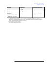
b. N is the LO multiplication factor. For negative mixing modes (as indicated by the “−” in the
“Harmonic Mixing Mode” column), the desired 1st LO harmonic is higher than the tuned fre-
quency by the 1st IF (5.1225 GHz for band 0, 322.5 MHz for all other bands).
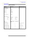
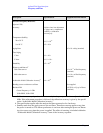
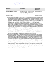
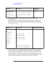
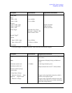
Description Specifications Supplemental Information
Standard Frequency Reference
Accuracy ±[(time since last adjustment × aging
rate) + temperature stability +
calibration accuracy
a
]
Temperature Stability
20 to 30 °C
±2 × 10
−6
5 to 50 °C
±2 × 10
−6
Aging Rate
±1 × 10
−6
/year
b