Chapter 7 109
Phase Noise Measurement Application
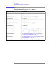
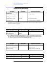
General Specifications
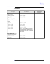
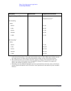
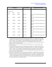
Description Specifications Supplemental Information
Measurement Accuracy
Phase Noise Density Accuracy
a
b
Default settings
c
Overdrive On setting
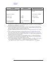
a. This does not include the effect of system noise floor. This error is a function of the signal (phase noise
of the DUT) to noise (analyzer noise floor due to phase noise and thermal noise) ratio, SN, in decibels.
The function is: error = 10 × log(1 + 10
−SN/10
)
For example, if the phase noise being measured is 10 dB above the measurement floor, the error due to
adding the analyzer’s noise to the UUT is 0.41 dB.
b. Offset frequency errors also add amplitude errors. See the Offset frequency section, below.
c. The phase noise density accuracy is derived from warranted analyzer specifications. It applies with
default settings and a 0 dBm carrier at 1 GHz. Most notable about the default settings is that the Over-
drive (in the advanced menu of the Meas Setup menu) is set to Off.
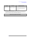
±0.50 dB
±0.60 dB (nominal)
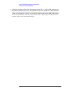
RMS Markers
See equation
d
d. The accuracy of an RMS marker such as “RMS degrees” is a fraction of the readout. That fraction, in
percent, depends on the phase noise accuracy, in dB, and is given by 100 × (10
PhaseNoiseDensityAccuracy /
20
− 1). For example, with +0.30 dB phase noise accuracy, and with a marker reading out 10 degrees
RMS, the accuracy of the marker would be +3.5% of 10 degrees, or +0.35 degrees.


