


Chapter 1 43
Agilent EXA Signal Analyzer
Dynamic Range
c. Reference level and off-screen performance: The reference level (RL) behavior differs from
some earlier analyzers in a way that makes this analyzer more flexible. In other analyzers, the
RL controlled how the measurement was performed as well as how it was displayed. Because
the logarithmic amplifier in these analyzers had both range and resolution limitations, this
behavior was necessary for optimum measurement accuracy. The logarithmic amplifier in this
signal analyzer, however, is implemented digitally such that the range and resolution greatly
exceed other instrument limitations. Because of this, the analyzer can make measurements
largely independent of the setting of the RL without compromising accuracy. Because the RL
becomes a display function, not a measurement function, a marker can read out results that are
off-screen, either above or below, without any change in accuracy. The only exception to the
independence of RL and the way in which the measurement is performed is in the input atten-
uation setting: When the input attenuation is set to auto, the rules for the determination of the
input attenuation include dependence on the reference level. Because the input attenuation
setting controls the tradeoff between large signal behaviors (third-order intermodulation, com-
pression, and display scale fidelity) and small signal effects (noise), the measurement results
can change with RL changes when the input attenuation is set to auto.
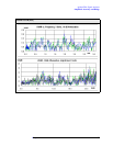
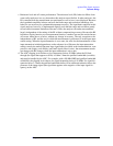
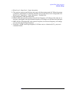
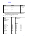
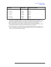
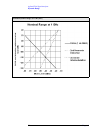
d. The ADC clipping level declines at low frequencies (below 50 MHz) when the LO feed
through (the signal that appears at 0 Hz) is within 5 times the prefilter bandwidth (see table)
and must be handled by the ADC. For example, with a 300 kHz RBW and prefilter bandwidth
at 966 kHz, the clipping level reduces for signal frequencies below 4.83 MHz. For signal fre-
quencies below 2.5 times the prefilter bandwidth, there will be additional reduction due to the
presence of the image signal (the signal that appears at the negative of the input signal fre-
quency) at the ADC.