


80 Intel Blade Server Fibre Channel Switch Module SBCEFCSW / FC Expansion Card SBFCM Guide
6. Connect the Fibre Channel devices to the switch module.
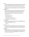
7. In the Edit Zoning window, make the necessary zoning changes.
Replacing a failed switch module in a fabric
Complete the following steps to replace a failed switch module for which an archive is available. See
“Restoring a switch module” on page 121 and “Archiving a switch module” on page 102 for more information.
1. Remove the failed switch module. For more information, see the
Installation Guide.
2. Install the new replacement switch module. For more information, see the
Installation Guide.
3. Log in to the fabric through the replacement switch module. In the Topology window, select the
replacement switch module from the fabric tree.
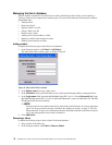
4. Click
Switch / Restore.
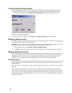
The Restore Switch window opens.
5. In the Restore Switch window, type a name or select the archived switch configuration file to copy to the
switch module. For more information, see “Archiving a switch module” on page 102.
6. Click
OK to write the configuration file to the switch module.
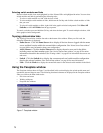
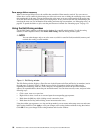
Deleting switch modules and links from the Topology display
The SAN Utility does not automatically delete switch modules or links that have failed or that are physically
removed. In this case, you can delete switch modules and links in the Topology window to bring the display up
to date. If you delete a switch or a link that is still active, the SAN Utility restores it automatically. You can
also refresh the display.
Complete the following steps to delete a switch module in the Topology window:
1. Select one or more switch modules in the Topology window.
2. Click
Switch / Delete.
Complete the following steps to delete a link:
1. Select one or more links in the Topology window.
2. Click
Switch / Delete.
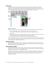
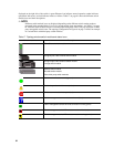
Displaying fabric information
The Topology window is the primary tool for monitoring a fabric. The graphics window of the Topology
window provides status information for switch modules, interswitch links, and the Ethernet connection to the
network management workstation.
The data window tabs show name server, switch, and active zone set information. The Active Zoneset tab
shows the zone definitions for the active zone set. See “Switch Data window” on page 94 and “Name Server
Data window” on page 108 for information about the Switch Data and Name Server Data windows.
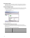
Fabric status
The fabric updates the Topology and Faceplate windows by forwarding changes in status to the network
management workstation as they occur. Use the fabric to update the display status, or you can refresh the
display at any time. To refresh the Topology window, use one of the following methods:
• In the Topology window, click
Refresh.
• Click
View / Refresh.
•Press the F5 key.
• Right-click anywhere in the background of the Topology window. Select
Refresh Fabric from the pop-
up menu.
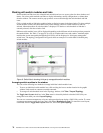
The Topology window displays switch module and status icons that provide status information about switches,
interswitch links, and the Ethernet connection. The switch module icons indicate different vendor switches and
switch types. The switch module status icons, displayed on the left side of a switch, vary in shape and color.
Each switch module that is managed by an Ethernet Internet protocol (IP) has a colored Ethernet icon that is