


115
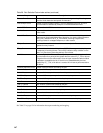
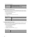
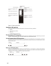
Figure 21. Switch module LEDs
Heartbeat LED patterns
The heartbeat LED uses different flash patterns to indicate the following conditions:
• Normal
• Internal firmware failure
• Fatal error
• Configuration file system error
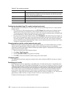
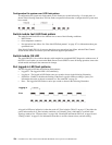
Normal (all pass) LED flash pattern
If POST diagnostics pass and the switch module processor is operating correctly, the switch will go to normal
operation, and the heartbeat LED will flash at a steady rate of one flash per second.
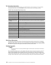
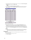
Internal firmware failure LED flash pattern
An internal firmware failure flash pattern is two flashes per second followed by a 2-second pause, as shown in
the following illustration. The two-flash error pattern indicates that the firmware has failed and that the switch
module must be reset.
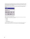
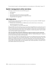
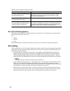
Fatal error LED flash pattern
A fatal error flash pattern is three flashes per second followed by a 2-second pause, as shown in the following
illustration. The three-flash error pattern indicates that a fatal error has made the switch module inoperable. If
a fatal error occurs, contact your technical support representative.