


151
5. Disconnect the switch modules one at a time. To do this, remove all cables connected to the switch
module; then, pull the release lever all the way down. Slide the switch module out of the bay
approximately 1 inch.
✏ NOTE
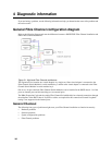
The minimum configuration is:
• unit (media tray may be connected).
• power module in bay 1.
• management module.
The Blade Server Chassis SBCE can be checked with the management module WEB interface at each stage as
components are removed, and will work in the minimal configuration. If the minimal configuration does not
work, do the following.
1. Recheck the management module network settings.
2. Disconnect the media tray and slid it out of the bay approximately 1 inch.
✏ NOTE
The front and rear panel LEDs will not function with the media tray removed.
3. Move the power module to bay 2.
4. Remove and reconnect the power cord to the power module.
5. Replace the management module.
6. Replace the power module.
7. Replace the midplane.
Problem determination tips
Due to the variety of hardware and software combinations that can be encountered, use the following
information to assist you in problem determination. If possible, have this information available when
requesting assistance from Service Support and Engineering functions.
• Machine type and model
• Microprocessor or hard disk upgrades
• Failure symptom
— Do diagnostics fail?
— What, when, where, single, or multiple systems?
— Is the failure repeatable?
— Has this configuration ever worked?
— If it has been working, what changes were made prior to it failing?
— Is this the original reported failure?
• Diagnostics version
— Type and version level
• Hardware configuration
— Print (print screen) configuration currently in use
—BIOS level
• Operating system software
— Type and version level