


100 Intel Blade Server Fibre Channel Switch Module SBCEFCSW / FC Expansion Card SBFCM Guide
on page 26 for information about the switch module keyword and the Domain ID Lock and Principal Priority
parameters.
If you connect a new switch module to an existing fabric with its domain ID unlocked and a domain conflict
occurs, the new switch module will be isolated as a separate fabric. However, you can remedy this by resetting
the new switch module or taking it offline then back online. The principal switch module will reassign the
domain ID, and the switch will join the fabric.
✏ NOTE
Domain ID reassignment is not reflected in zoning that is defined by domain ID and port number pair.
You must reconfigure zones that are affected by domain ID reassignment.
Broadcast support
Broadcast is supported by the switch module, which enables TCP/IP support. Broadcast is implemented using
the proposed standard specified in Multi-Switch Broadcast for FC-SW-3, T11 Presentation Number T11/02-
031v0. The FSPF is used to set up a fabric spanning tree used in transmission of broadcast frames. Broadcast
frames are retransmitted on all ISLs indicated in the spanning tree and all online F/FL_Ports. Broadcast zoning
is supported with ACL and VPF hard zones. When a broadcast frame is received, these hard zones are
enforced at the F/FL_Port. If the originator of the broadcast is in a hard zone, the frame is retransmitted on all
online F/FL_Ports within the hard zone. If the originator of the broadcast frame is not in a hard zone, the frame
is retransmitted on online F/FL_Ports that are not in a hard zone.
In-band management
In-band management is the ability to manage switch modules across interswitch links. If you disable in-band
management on a particular switch module, you can no longer communicate with that switch module by
means other than a direct Ethernet or serial connection.
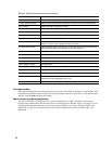
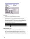
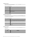
Timeout values
The switch module timeout values determine the timeout values for all external ports on the switch. Table 22
describes the switch module timeout parameters. R_A_TOV, R_T_TOV, or E_D_TOV values must be the
same for all switch modules in the fabric.
✏ NOTE
Timeout values can be changed only if the switch module operational state is offline.
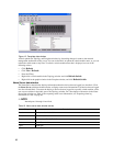
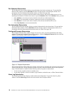
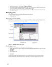
Network properties
Use the Network Properties window shown in Figure 16 on page 101 to change IP and SNMP configuration
parameters. After making changes, click OK to put the new values into effect. To open the Network Properties
window, click Switch / Network Properties.
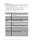
Table 22. Timeout values
Parameter Description
R_A_TOV Resource Allocation Timeout. Represents the maximum time a frame can be
delayed in the fabric and still be delivered. The default is 10000 milliseconds.
R_T_TOV Receiver Transmitter Timeout. The amount of time that Sync can be lost
between two ports before Link Failure is detected. The default is 100
milliseconds.
E_D_TOV Error Detect Timeout. Represents the maximum round trip time that an operation
between two N_Ports requires. The default is 2000 milliseconds.