


73
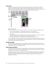
Working status indicator
The working status indicator as shown in Figure 1 on page 69 is in the lower-right corner of the Topology
window and shows when the network management workstation is exchanging information with the fabric. As
conditions change, the fabric forwards this information to the network management workstation where it is
reflected in the various displays.
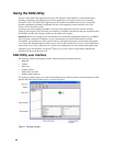
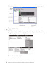
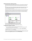
Using the Topology window
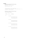
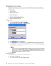
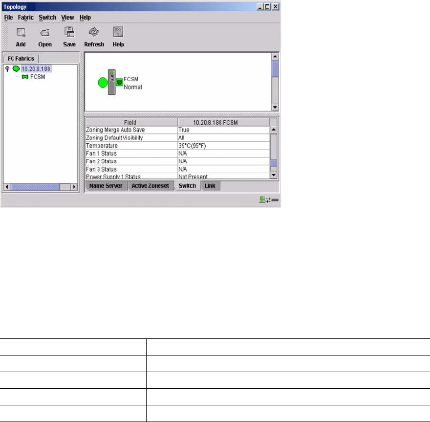
The Topology window shown in Figure 5 polls the selected fabric and displays its topology. switch modules
and interswitch links (ISL) are displayed in the graphic window and use color to indicate status. The following
functional elements are displayed in the Topology window when you click on the Data window tabs:
• Switch module and link status
• Working with switch modules and links
• Topology data windows
Figure 5. Topology window
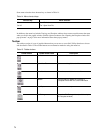
Fibre Channel switch module and link status
The Fibre Channel switch module icon shape and color provide information about the switch and its
operational state. In the Topology window, lines represent links between switch modules. See Table 16 for
Fibre Channel switch module and link status and “Fabric status” on page 80 for more information about other
Topology window icons.
Table 16. Fibre Channel switch module and link status indicators
Switch module icon color Status
Green Normal Fibre Channel switch operation
Amber Operational with errors
Red Inactive or Fibre Channel switch failure
Blue Unknown Fibre Channel device