


129
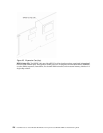
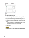
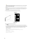
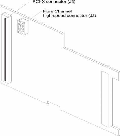
The following illustration shows the components on the bottom of the Expansion Card.
Figure 26. Expansion Card (bottom)
PCI-X connector (J3): This connector is a 64-bit PCI-X interface with a 200-pin board-to-board connector
that is connected to the blade server.
Fibre Channel high-speed connector (J2): Communication signals are routed from the blade server through
the Fibre Channel high-speed connector on the Expansion Card to switch-module bay 3 and bay 4 in the Blade
Server Chassis SBCE.
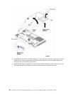
Installing the Expansion Card
This chapter provides detailed instructions for installing the Expansion Card in your blade server.
Installation guidelines
Before you begin installing the Expansion Card in your blade server, read the following information:
• Read “Safety and regulatory information” on page iii and “Handling electrostatic discharge-sensitive
devices” on page v. This information will help you work safely with your blade server and options.
• Have a small flat-blade screwdriver and a Phillips screwdriver available.