


141
4 Diagnostic information
If you are having a problem, use the following information to help you determine the cause of the problem and
the action to take.
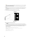
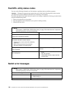
General Fibre Channel configuration diagram
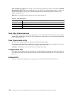
Refer to the following diagram and note the differences between a SBCEFCSW Fibre Channel installation and
other Fibre Channel installations:
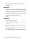
Figure 31. High level Fibre Channel architecture
The Expansion Card contains two virtual adapters on a single card. One virtual adapter is connected to the
Fibre Channel Switch Module in switch module bay 3 and the other virtual adapter is connected to the Fibre
Channel Switch Module in switch module bay 4.
One or two 16-port switched (Fiber Channel Switch Modules) can be installed in the SBCE chassis. 14 of the
ports are internal ports and the remaining two are external ports.
The HBA (Expansion Card) and the switch (Fibre Channel Switch Module) have internal connections through
the mid-plane of the SBCE chassis. No SFPs or cables are required for this connection. External Loopback
testing is not supported on the internal ports.
General Checkout
The following four types of problems might cause your Fibre Channel installation to function incorrectly:
• Hardware problems
• Software problems
• System configurations problems
• Fibre Channel problems