


124 Intel Blade Server Fibre Channel Switch Module SBCEFCSW / FC Expansion Card SBFCM Guide
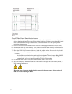
Mapping port locations and software numbering
Your switch module has two external Fibre Channel ports (external Fibre Channel port 1 and external Fibre
Channel port 2) and 14 internal Fibre Channel ports that connect to each of the 14 blade server bays (ports 1 to
14). The SAN Utility and CLI for the switch module require port numbering from 0 to 15. The SNMP
monitoring agent for the switch module numbers the ports from 1 to 16.
Port mapping
Table 37 shows the mapping of switch module port numbering and whether the port has the capability to be
configured.
✏ NOTE
The Fibre Channel ports that connect to each of the blade server bays (1 through 14) are fixed 2 Gbps
F_Port configurations. Only the administrative state for these ports can be changed.
Table 37. Port mapping
Switch module physical port
connection
SAN Utility and CLI logical
port number
SNMP port
numbering
Configurable
External port 1 0 (Ext1:0*) 1 Yes
Blade server bay 1 1 2 No
Blade server bay 2 2 3 No
Blade server bay 3 3 4 No
Blade server bay 4 4 5 No
Blade server bay 5 5 6 No
Blade server bay 6 6 7 No
Blade server bay 7 7 8 No
Blade server bay 8 8 9 No
Blade server bay 9 9 10 No
Blade server bay 10 10 11 No
Blade server bay 11 11 12 No
Blade server bay 12 12 13 No
Blade server bay 13 13 14 No
Blade server bay 14 14 15 No
External port 2 15 (Ext2:15*) 16 Yes
* Indicates a symbolic port name if it is different from the logical port number.