


39
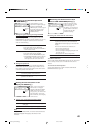
Note:
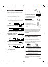
When shipped from the factory, the DIGITAL IN terminals can be used
as the digital input for the following components:
• DIGITAL 1 (coaxial): For DVD player
• DIGITAL 2 (optical): For CD player
• DIGITAL 3 (optical): For digital TV broadcast tuner
• DIGITAL 4 (optical): For CD recorder
• DIGITAL 5 (optical): For MD recorder
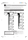
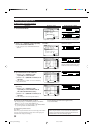
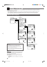
Preparing for the Component Video Input
—COMPONENT IN (8)
When you use the component
video input, you have to register
what components you have
connected to the component
input terminals.
Without setting this correctly,
you cannot view the correct input
on the TV.
7
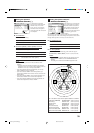
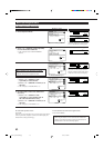
Setting the component video input terminals
Select the components connected to the COMPONENT 1
(DVD) and COMPONENT 2 video input terminals.
• Each time you press # (RIGHT) or @ (LEFT), the component
name changes as follows:
1 DVD 2 – – – “ 1 DVD 2 DBS* “
1 DVD 2 VCR1 “ 1 DBS* 2 – – – “
1 DBS* 2 VCR1 “ 1 VCR1 2 – – – “
1 – – – 2 – – – “ (back to the beginning)
Notes:
*
When you have connected the DBS tuner to the COMPONENT
1 (DVD) or COMPONENT 2 video input terminals, change the
source name from “TV” to “DBS.”
To change the source name, see “Changing the Source Name”
on page 25.
• When you have not connected any component, select “– – –.”
• If you have not made this setting correctly, the AV COMPU LINK
remote control system cannot operate properly. (See page 61.)
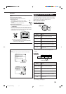
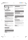
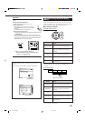
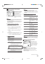
Turning On and Off the Video Output
—VIDEO POWER (9)
On this submenu screen, you can
turn on or off the power supply
to the video output circuit built
in this unit.
7
Turning on or off the power supply to the video
circuit
Select one of the following:
ON : Normally select this.
Power is supplied to the built-in video output circuit.
OFF : Select this not to supply power to the built-in video
output circuit while playing an audio source.
With this setting, noise will be reduced while playing an
audio source.
Note:
Even if “VIDEO POWER” is set to “OFF,” power will be supplied to
the video circuit when on-screen display menus are used.
7
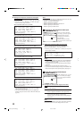
Setting the component connected to the digital
optical terminals
Set the components connected to the digital optical terminals.
• Each time you press # (RIGHT) or @ (LEFT), the digital
component names change as follows:
When “COAXIAL INPUT” is set to “DVD”
2 CD 3 TV (or DBS*) 4 CDR 5 MD “
2 CD 3 TV (or DBS*) 4 CDR 5 VCR1 “
2 CD 3 TV (or DBS*) 4VCR1 5 MD
**
“
2 CD 3 VCR1 4 CDR 5 MD
**
“
2 VCR1 3 TV (or DBS*) 4 CDR 5 MD
**
“
(back to the beginning)
When “COAXIAL INPUT” is set to “CD”
2 DVD 3 TV (or DBS*) 4 CDR 5 MD “
2 DVD 3 TV (or DBS*) 4 CDR 5 VCR1 “
2 DVD 3 TV (or DBS*) 4 VCR1 5 MD
**
“
2 DVD 3 VCR1 4 CDR 5 MD
**
“
2 VCR1 3 TV (or DBS*) 4 CDR 5 MD
**
“
(back to the beginning)
When “COAXIAL INPUT” is set to “TV” or “DBS”
*
2 CD 3 DVD 4 CDR 5 MD
**
“
2 CD 3 DVD 4 CDR 5 VCR1 “
2 CD 3 DVD 4 VCR1 5 MD
**
“
2 CD 3 VCR1 4 CDR 5 MD
**
“
2 VCR1 3 DVD 4 CDR 5 MD
**
“
(back to the beginning)
When “COAXIAL INPUT” is set to “CDR”
2 CD 3 TV (or DBS*) 4 DVD 5 MD
**
“
2 CD 3 TV (or DBS*) 4 DVD 5 VCR1 “
2 CD 3 TV (or DBS*) 4 VCR1 5 MD
**
“
2 CD 3 VCR1 4 DVD 5 MD “
2 VCR1 3 TV (or DBS*) 4 DVD 5 MD
**
“
(back to the beginning)
When “COAXIAL INPUT” is set to “MD”
**
2 CD 3 TV (or DBS*) 4 CDR 5 DVD “
2 CD 3 TV (or DBS*) 4 CDR 5 VCR1 “
2 CD 3 TV (or DBS*) 4 VCR1 5 DVD “
2 CD 3 VCR1 4 CDR 5 DVD “
2 VCR1 3 TV (or DBS*) 4 CDR 5 DVD “
(back to the beginning)
When “COAXIAL INPUT” is set to “VCR1”
2 CD 3 TV (or DBS*) 4 CDR 5 MD
**
“
2 CD 3 TV (or DBS*) 4 CDR 5 DVD “
2 CD 3 TV (or DBS*) 4 DVD 5 MD
**
“
2 CD 3 DVD 4 CDR 5 MD
**
“
2 DVD 3 TV (or DBS*) 4 CDR 5 MD
**
“
(back to the beginning)
*
If you have changed the source name from “TV” to “DBS,”
“DBS” appears (see page 25).
**
If you have connected an MD recorder to the digital input
terminal, change the source name to “MD” from “TAPE” (see
page 25).
COMPONENT IN
COMPONENT INPUT:
1DVD 2–––
:OPERATE
:BACK
VIDEO POWER
VIDEO POWER : ON
:OPERATE
:BACK
EN33-40_RX-DP10VBK[J]_f 01.6.19, 11:35 AM39