


Front Panel Operation, cont’d
USP 507 • Front Panel Operation
3-16
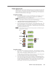
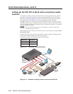
Setting Up the USP 507 to Work with an Auxiliary Audio
Switcher
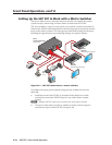
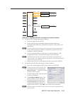
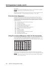
An auxiliary switcher, such as an Extron SW 8A, can be connected to the USP 507
for audio routing, and controlled via the rear panel 9-pin D-sub Aux Sw Follow
(RS-232) port (see n on figure 2-2). When the USP 507 switches inputs by RS-232,
IP, or front panel, the USP 507 sends the corresponding switch command
(SIS:
X!
!) via the Aux Sw Follow port to the auxiliary switcher. The port can also
transmit the audio mute command (1Z) to the auxiliary switcher when the USP 507
video is muted or frozen, and when the video is unmuted or unfrozen, a command
is sent to unmute the audio.
N
This port cannot directly accept SIS commands nor report the status of the
connected auxiliary switcher.
The auxiliary switcher must be connected to the Aux Sw Follow port using a NULL
RS-232 cable only.
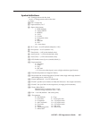
Connect the audio input sources to the auxiliary audio switcher, ensuring that the
video input number matches the audio input number.
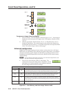
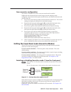
Connect the control host with the pinout as shown below.
Controller Pin USP 507 Pin
2 (Rx) 3 (Tx)
3 (Tx) 2 (Rx)
5 (Gnd) 5 (Gnd)
Figure 3-10 — Controller to USP 507 pinout
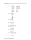
50/60 Hz
100-240V VAC 2A MAX
RGB/R-Y, B-Y, Y
LAN
RS-232-1
2
1
R-Y
R/
4
3
R
/R-Y
R
/R-Y
G/Y
VID
G
/Y
B
/B-Y
B/C
B-Y
H/HV
VID
/Y
V
B-Y
C
HDSDI/SDI
H V
S
I
N
P
U
T
O
U
T
P
U
T
AUX SW FOLLOW
RGB
RGB
VID
/Y
5
MTP
DVI-D
VID
/Y
DVI
OUT
C
7
8
PC
VIDEO / AUDIO SWITCHER
CONF/SAVE
EXECUTIVE
MODE
8
7
6
5
4
3
2
1
AUDIO
-dB
+dB
SW SERIES
Conference
Display
Sound System
BASSLEVEL
TREBLE
MINI POWER AMPLIFIER
MPA 401
Extron
USP 507
Universal Signal
Processor
Projector
DVD
Video Conference
Codec
Laptop
Extron
SW 8 A
Switcher
RESET
Extron
MPA 401
Mini Power
Amplier
Video
Audio
Control
RS-232
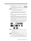
Figure 3-11 — Example auxiliary switcher connected to USP 507