


2-5
USP 507 • Installation
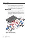
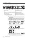
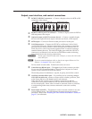
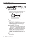
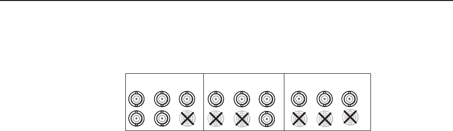
Output, user interface, and control connections
h
RGB/YUV-HD BNC connectors — Connect a display to these for RGB or HD
component video output.
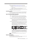
RGBHV
H/
HV
R
/R-Y
V
G
/Y
B
/B-Y
R
/R-Y
V
G
/Y
RGBS video
H/
HV
B
/B-Y
R
/R-Y
G
/Y
B/
B-Y
RGsB/Component Video
(Y, R-Y, B-Y)
H/
HV
V
S
S
S
i
RGB/YUV-HD 15-pin VGA connector — Connect a display to this for RGB or
HD component video output.
j
Optional output card (DVI connector shown) — Connect a suitable display
device to this optional format output connector (as shown, a DVI output).
k
MTP output — Connect an Extron twisted pair receiver to this port
l
LAN Ethernet port — Connect the USP 507 to an Ethernet LAN or WAN
via this RJ-45 connector. Ethernet control allows the operator to control the
processor from a remote location. When connected to an Ethernet LAN or
WAN, the device can be accessed and operated from a computer running a
standard Internet browser. The Link LED lights green when the USP 507 is
connected to an Ethernet LAN, and the Act LED flickers amber, indicating
data transmission as the devices communicate.
C
Do not connect the MTP cable to the LAN port, or connect the LAN cable
to the MTP port.
N
Do not use standard telephone cables, as they do not support Ethernet or Fast
Ethernet. See Appendix B for correct cabling.
Do not stretch or bend cables. Transmission errors can occur.
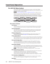
m
Control device (RS-232) port — The upper 9-pin D-sub connector provides
for two-way RS-232 communication. Connect a host computer or control
system to it for serial RS-232 or RS-422 control.
The default protocol is 9600 baud, 1 stop bit, no parity, and no flow control.
n
Auxilliary switcher follow port — For auxiliary device switching, using a
NULL RS-232 cable only, connect an Extron audio switcher/processor, such
as the Extron SW 8A, to the lower 9-pin D-sub connector .
When the USP 507 switches input via either a control device RS-232
command or front panel control, the USP 507 and the connected auxiliary
device switch inputs. When video is muted or unmuted, frozen or unfrozen,
a corresponding audio mute/unmute command is sent to the auxiliary
switcher.
o
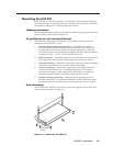
Reset button and LED — This button is used to reset the switcher to any one
of four different states. The LED indicates the status during the resetting
procedure. Refer to the “Resetting the Unit with the Reset Button” section, on
page 2-7, for full details.