


Installation, cont’d
USP 507 • Installation
2-6
Installation and cabling
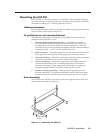
Step 1 — Mount the unit
Turn off or disconnect all equipment power sources and rack mount the
USP 507. See page 2-3.
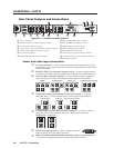
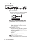
Step 2 — Connect inputs
Connect inputs from video sources to the applicable connectors marked
“Inputs” (see page 2-4, b to g for connector types).
Step 3 — Connect outputs
Connect video output devices to the applicable connectors marked “Outputs”
(see page 2-5, h to k for connector types).
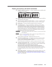
Step 4 — Connect control devices
LAN Ethernet port — Connect to an Ethernet LAN or WAN via this RJ-45
connector
l
to control the processor from a remote location, using a PC’s
Internet browser. See Appendix B for network cable termination method.
Ethernet connection indicator LEDs marked indicate the status of the Ethernet
connection. The green LED lights when connected to an Ethernet LAN, and
the amber LED flickers as the devices communicate.
Control device port — For serial RS-232 or RS-422 control, connect a host
computer or control system via the upper 9-pin D-sub connector m.
RS-232 protocol (default values):
• 9600 baud • 1 stop bit • no parity • 8 data bits • no flow control.
N
See chapter 4, “SIS Programmer’s Guide” for definitions of the SIS commands.
See chapter 5, “USP 507 Software” to install and use the control software.
Step 5 — Connect auxiliary device
RS-232 port — Connect an auxiliary device, such as an Extron switcher, to the
lower RS-232 port n, using a NULL RS-232 cable only.
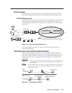
Step 6 — Connect power
AC power connector — Plug in a standard IEC power cord from a 100 to
240 VAC, 50 - 60 Hz power source into this receptacle
a
.