Hardware Implementation
2-16 Quantum DLT 7000 Tape Drive
Note that the power supply of the tabletop unit has an auto-sensing feature; no
adjustment or switch setting changes are required for different ac sources.
Refer to Figure 2-6. Connect one end of the power cord to the power connector on
the back of the drive. Connect the other end of the cord to the ac outlet.
2.4 DRIVE CONTROLS AND LIGHT EMITTING DIODES (LEDS)
This section identifies the front panel controls and LEDs and describes their
functionality. It also explains density selection.
2.4.1 Front Panel Controls and LEDs
This section describes the front panel controls and Light Emitting Diodes (LEDs)
used to operate the tape drive; all controls and LEDs are located on the tape
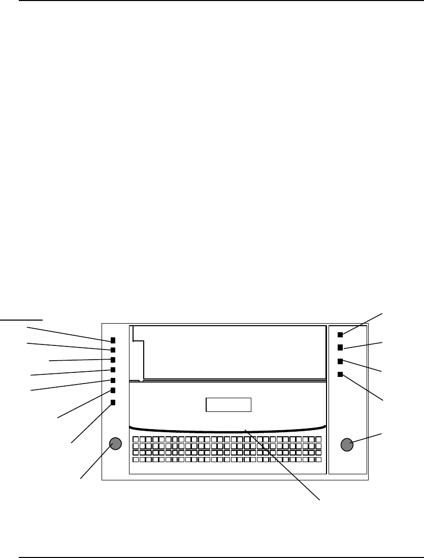
drive’s front panel. Figure 2-8 shows the locations of the controls and LEDs on
the front panel; Tables 2-6 through 2-8 describe control and LED functionality.
In addition to the controls and LEDs, the tape drive also has an audible beeper
that signals when the drive’s cartridge insert/release handle can be safely used.
Use these controls and LEDs to operate the tape drive and monitor the tape
drive’s activities.
Figure 2-8 DLT 7000 Front Panel
Compress LED
Density Select Button
Write-Protected LED
Use Cleaning Tape LED
Operate Handle LED
Unload Button
Cartridge Insert/Release Handle
Density LEDs
2.6
6.0
10.0/15.0


