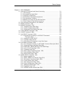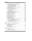
Table of Contents
Quantum DLT 7000 Tape System
xii
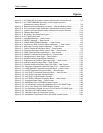
Figures
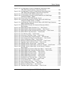
Figure 2–1 DLT 7000 SCSI ID Jumper Location (Rackmount Version Shown)............... 2-5
Figure 2–2 DLT 7000 TERMPWR and Parity Check Jumper Locations
(Rackmount Version Shown).................................................................. 2-6
Figure 2–3 Rackmount Drive Mounting Locations – Side and Bottom Views............... 2-8
Figure 2–4 SCSI and Power Cable Connectors (Rackmount Version Shown)............... 2-9
Figure 2–5 Loader Connector Block Location (Rackmount Version Shown)................ 2-12
Figure 2–6 Tabletop Back Panel............................................................................... 2-13
Figure 2–7 AC Power Cord Connector Types............................................................ 2-15
Figure 2–8 DLT 7000 Front Panel.............................................................................. 2-16
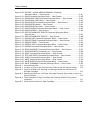
Figure 4–1 Extended Message — Data Format.......................................................... 4-4
Figure 4–2 IDENTIFY Message — Data Format........................................................... 4-7
Figure 4–3 IGNORE WIDE RESIDUE Message — Data Format ..................................... 4-8
Figure 4–4 Synchronous Data Transfer Request Message — Data Format ................. 4-12
Figure 4–5 Wide Data Transfer Request Message — Data Format............................. 4-13
Figure 5–1 Typical Command Descriptor Block — Data Format.................................. 5-4
Figure 5–2 Command Descriptor Block Control Field — Data Format......................... 5-6
Figure 5–3 ERASE Command Descriptor Block — Data Format................................... 5-15
Figure 5–4 INQUIRY Command Descriptor Block — Data Format................................ 5-17
Figure 5–5 Standard Inquiry Data Page — Data Format............................................ 5-19
Figure 5–6 INQUIRY Vendor Unique Bytes Definitions................................................ 5-22
Figure 5–7 Supported Vital Product Data Pages Page — Data Format ....................... 5-24
Figure 5–8 Unit Serial Number Page (80h)— Data Format ......................................... 5-25
Figure 5–9 Firmware Build Information Page (VU) (C0h)— Data Format ..................... 5-26
Figure 5–10 Subsystem Components Revision Page (C1h) — Data Format .................. 5-27
Figure 5–11 LOAD UNLOAD Command Descriptor Block — Data Format.................... 5-30
Figure 5–12 LOCATE Command Descriptor Block — Data Format............................... 5-33
Figure 5–13 LOG SELECT Command Descriptor Block — Data Format......................... 5-35
Figure 5–14 LOG SELECT Log Page Header Format.................................................... 5-38
Figure 5–15 LOG SELECT Log Parameters Format...................................................... 5-39
Figure 5–16 LOG SENSE Command Descriptor Block — Data Format.......................... 5-43
Figure 5–17 Supported Pages Page — Data Format.................................................. 5-47
Figure 5–18 Read/Write Error LOG SENSE Header Format.......................................... 5-48
Figure 5–19 Log Parameters Format for Read/Write Error LOG SENSE Page................ 5-49
Figure 5–20 Last n Error Events LOG SENSE Header Format....................................... 5-52
Figure 5–21 Log Parameters Format for Last n Error Events LOG SENSE Page............. 5-53
Figure 5–22 TapeAlert LOG SENSE Header Format.................................................... 5-54
Figure 5–23 TapeAlert Page Log Parameters Format................................................. 5-55
Figure 5–24 Read/Write Compression Ratio LOG SENSE Header Format...................... 5-58


