


Hardware Implementation
2-12 Quantum DLT 7000 Tape Drive
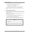
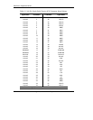
Table 2–4 4-Pin Power Connector Pin Assignments
Pin Number Signal Name
1 +12 VDC
2 Ground (+12 V return)
3 Ground (+5 V return)
4 +5 VDC
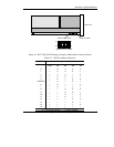
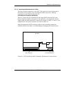
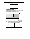
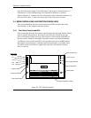
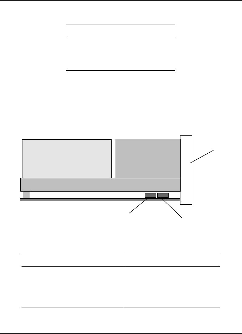
Optional Loader Connector (Rackmount)
The loader connector provides signals to be used when the tape drive is part of a
loader/library configuration. Figure 2-5 shows the location of the connector; pin
assignments for the loader connector are listed in Table 2-5.
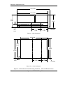
Figure 2–5 Loader Connector Block Location (Rackmount Version Shown)
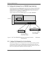
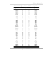
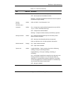
Table 2–5 10-Pin Loader Connector Pin Assignments
Signal Name Pin Number Pin Number Signal Name
Loader_Present L 1 6 Send_to_Loader (-) L
Rec_From_Loader (+) H 2 7 DEL23 L
Rec_From_Loader (-) L 3 8 DEL24 L
DEL27 L 4 9 DEL25 L
Send_to_Loader (+) H 5 10 DEL26 L
10-Pin Loader Connector
Front Panel
SCSI ID Jumper Block