


14
TASCAM HS-20
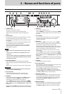
2 – Names and functions of parts
This BNC connector is for output of word clock thru/out and
video reference thru signals.
Use this to output a word clock signal (thru, 44.1 kHz, 48 kHz,
88.2 kHz, 96 kHz, 176.4 kHz or 192 kHz) or a video reference
signal (IN connector signal thru only).
Use the THRU/WORD OUT switch to set the signal output.
! 75Ω OFF/ON and THRU/WORD OUT switch
Use this switch to make the following settings.
o Whether or not the WORD/VIDEO IN connector has a
terminator (75Ω)
o The WORD/VIDEO output THRU/OUT setting (OUT is only
for WORD)
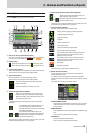
@ ETHERNET connector
Use this Ethernet connector to connect to a network for file
transfer and to control this unit from an external source.
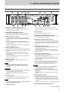
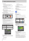
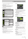
PARALLEL connector
The PARALLEL connector on the rear panel allows external
control of this unit. (A TASCAM RC-SS20 can also be connected.)
The pin assignments are as follows.
Pin
No.
Normal
RC-SS20 PonMode
I/O
1 GND GND
2 PLAY FLASH 1 I
3 STOP FLASH 2 I
4 RECORD FLASH 3 I
5 SKIP FWD FLASH 4 I
6 SKIP BWD FLASH 5 I
7 (Reserved) STOP I
8 FADER_START FADER_START I
9 (Reserved) (Reserved) O
10 TALLY_PAUSE TALLY_PAUSE O
11 TALLY_RECORD RESERVED O
12 TALLY_STOP TALLY_STOP O
13 TALLY_PLAY TALLY_PLAY O
14
REMOTE_SELECT,
H or Open
REMOTE_SELECT, L I
15 PAUSE FLASH 6 I
16 (Reserved) FLASH 7 I
17 AUX1, FF FLASH 8 I
18 AUX2, REW FLASH 9 I
19 AUX3, MARK FLASH 10 I
20 (Reserved) FLASH_PAGE I
21 (Reserved) (Reserved) O
22 TALLY_SD TALLY_SD
1
O
23 (Reserved) (Reserved) O
24 TALLY_CF TALLY_CF
2
O
25 +5V
3
+5V
3
I: Command input for transport control
Internal circuit, +5V pull-up
Triggers from a low input level of 50 msec or more
O: Command output, for tally output
The internal circuit is open collector
(10Ω output impedance)
Low command output when operating
20V dielectric strength, 35mA maximum current
1For RC-SS20, assigned to CF indicator
2For RC-SS20, assigned to CD indicator
3+5V: maximum supplied current is 50 mA
When REMOTE Select (pin 14) is set to high, it can be used as an
ordinary parallel controller.
When set to low, flash start mode is enabled.
In addition, depending on the high/low setting of the Flash
Page (pin 20), the key assignments are as follows.
Pin 14 Pin 20 Flash start take
Low
High 1–10
Low Low 11–20
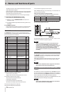
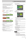
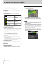
The following example is of a connection that uses a fader to
start and stop playback of this unit.
For information about the assignment of AUX 1–3 (pins 17–19)
functions, see “PARALLEL page” on page 85.
NOTE
When controlling this unit with an external device that
is connected to the PARALLEL connector, if the unit is
stopped, you can start recording immediately by simultane-
ously inputing PLAY and RECORD signals. In addition, by
simultaneously inputting PLAY and RECORD signals
during playback in timeline mode, you can start overwrite
recording.
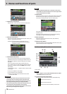
RS-232C connector
The RS-232C connector on the rear panel can be connected to
an RS-232C connector on a computer to allow control of this
unit from that computer.
Make settings related to communication on the RS–232C page
of the REMOTE SETUP screen. (See “RS–232C page” on page
85.)
NOTE
Please contact TASCAM customer support for information
about this unit’s RS-232C command protocol.
RS-422 connector (attached to optional SY-2
board)
The optional SY-2 board is equipped with an RS-422 connector.
You can control this unit remotely by installing an SY-2 board in
this unit and connecting the RS-422 connector to a controller or
editor compatible with the SONY P2 protocol (RS-422).
Make settings related to operation on the REMOTE SETUP screen
RS–422 page. (See “RS–422 page” on page 86.)
NOTE
Please contact TASCAM customer support for information
about this unit’s protocol compatibility.