


Application Notes
58
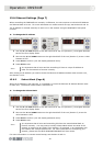
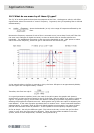
16.2. What do we mean by all these Q types?
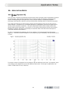
The “Q” of an audio equaliser describes the steepness of the filter - the degree to which it will affect
signals either side of its nominal or “centre” frequency. In general, the Q of a peaking filter is defined
mathematically:
as, where the bandwidth (in Hz) is the range of frequencies affected by the
filter.
Because the frequency response of such a filter is a smooth curve (not a sharp “brick wall” filter like
the ones in an analogue-to-digital converter) we have to decide how we choose to define the
bandwidth. The established convention is that we use the bandwidth to the “-3dB” points on either
side of the centre frequency, where the gain is 3dB less than the maximum gain.
In the example above, the filter is centred on 1kHz, the lower 3dB point is at approximately 800Hz,
and the upper one is at approximately 1.25kHz.
Therefore, this filter has a Q of:
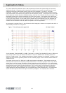
In a typical parametric equaliser (and in the case of the Helix system the graphic and dynamic
sections too) we have a manual control for the Q of the filter, and this allows us to set any Q that we
require. In general, high-Q, narrow filters are used for notching out problem frequencies without
affecting the programme material too much. While gentler low-Q filters are useful for adjusting the
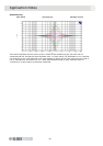
tonal balance. In the case of graphic equalisers there is another issue - that of interaction between
adjacent bands. In general, lower-Q filters will blend together more smoothly, but higher-Q filters
provide more selective control of problems - at the expense of more frequency response ripple.
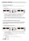
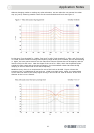
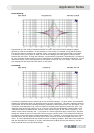
So far so simple - but why the different types? This is due to the way in which the Q of the filter
varies (or not) when the gain control is adjusted. There are three modes available in the Helix
system, which we term Proportional, Constant, and Symmetrical Q.