


Application Notes
56
If we now replace the parametric with a Helix equaliser and select the dynamic EQ, we have some
additional controls. Frequency and Q controls are as before, but now we have two pairs of controls
replacing the single cut and boost control; these are [low threshold] / [low level], and [high
threshold] / [high level]. If we set the frequency and Q controls to the area that we wish to control,
then the processor will monitor the signal level in that frequency range. If the signal level in this part
of the spectrum is below the [low threshold] setting, then the unit considers this a ‘quiet’ signal. The
EQ applied to the signal will be controlled by the [low level] control. If the signal level is above the
[high threshold] level, then the unit considers this a ‘loud’ signal, and will apply the amount of EQ set
by the [high level] control. If the signal level is between the two thresholds, then the equaliser will
seamlessly morph between the two equaliser settings in real time. Manual control over attack and
release times is available to set the speed of response to suit the application.
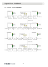
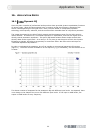
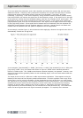
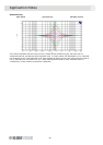
As an example, consider Figure 2, which shows the Helix applying a boost at low signal levels which is
automatically ‘wound out’ at high level.
In this example, [low threshold] is -20dBu, [low level] is +12dB, [high threshold] is set to -5dBu, and
[high level] is 0dB. Thus, the lowest trace shows an input at -25dBu with a standard parametric
boost of +12dB at 1kHz. The -20dBu trace shows an identical response, as expected. However, once
above this level the filter gradually fades out with increasing signal, until at all levels above 0dBu the
response is flat.
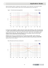
The shape of the curves for -5dBu and -10dBu require some explanation. These appear as they do
because of the nature of the frequency sweep measurement. The Helix equaliser uses a copy of the
actual filter in use for its level calculation, so that, depending on the Q of the filter, our input signals
are ‘ignored’ as we move away from the centre frequency by the correct amount. Thus, as the sweep
measurement moves across the centre frequency (1kHz in this case), the dynamic EQ is ramping
smoothly in and out again, leading to the curves in Figure 2. Note that if the level is outside the
range specified by the two thresholds, the unit behaves like a fixed parametric EQ. This means that
we do not have to guess how much EQ will eventually be applied - it is explicitly set in advance.