


Operation: DN9340E
24
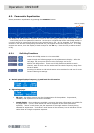
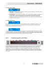
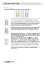
6.6. Metering
Comprehensive audio metering is provided by eight LED bargraph meters:
There are a pair of input meters (labelled “A” and “B” for audio channels A and B,
respectively) that show the input level immediately following the input gain
control. These can therefore be used as a guide for setting the input gain to
match the signal level being sent to the unit. With the input gain control set to
0dB (unity gain) then full-scale on the meter will occur at a signal level of +21dBu,
which is the maximum permissible signal level. The input meters incorporate a
red ‘clip’ LED that indicates signal clipping both on the actual input to the unit and
also after the gain control. This ensures that all possible clip conditions are
monitored irrespective of the setting of the gain control.
There are a pair of output meters (labelled “A” and “B” for audio channels A and
B, respectively) that show the output level from the unit. Full-scale on the meter
indicates maximum output from the unit, which corresponds to +21dBu. The
output meters also incorporate a red ‘clip’ LED. This indicates signal clipping
within the unit, and is monitored at all internal points where gain can be applied.
Thus, if a large amount of gain is added with one section of a parametric EQ,
resulting in a clipped signal, but the level is then reduced by a subsequent EQ
section, the clip LED will still illuminate to indicate the internal clip condition
despite the apparently safe output level. In this situation the input gain should be
reduced to provide sufficient headroom for the desired EQ characteristic. Note
that because these meters are on the output of the unit, they will show the effect
of any delay that has been selected.
There are four meters which show the action of the
dual-threshold
dynamic EQ system, one meter for each EQ section on each of the two audio
channels A and B. The dynamic EQ meters are calibrated in percentage terms,
from 0 to 100. If no dynamic EQ is selected or if the signal is below the ‘low’
threshold, then the meters will show 0% (that is, no LEDs illuminated). Under this
condition the dynamic EQ will be using the ‘low’ frequency response settings. If
the signal level is above the ‘high’ threshold, the relevant meter will indicate 100%
(fully illuminated) showing that the ‘high’ EQ settings are now being applied. If
the signal is between the two thresholds, then the EQ will be morphing between
the two EQ settings, and the meter indicates the signal level relative to the two
thresholds. Note that the effect of the attack and release controls is also indicated
on these meters - the height of the bar indicates the actual EQ being applied, so if
a slow release is set, for example, you will see the meter drop back slowly
following a peak.