


Controls, Connectors, Indicators: DN9344E
47
1
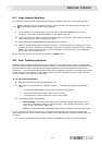
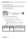
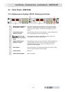
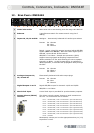
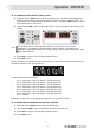
12. REAR PANEL: DN9344E
1 Mains inlet socket Mains inlet unit is auto sensing over the range 100-240V AC.
2 Ethernet 2-port Ethernet switch for remote control using Cat-5
cabling.
3 Inputs 1A, 1B, 2A and 2B
Analogue – electronically balanced XLR audio input sockets
Pinouts: Pin 1 Screen
Pin 2 Hot
Pin 3 Return
Digital – inputs 1A and 2A support incoming 96kHz AES/EBU
signals (AES IN 1 and AES IN 2). Note that when digital input is
selected, inputs 1B and 2B are inactive.
AES/EBU is 110 Ohms. Sample rate converters (SRCs)
support incoming signals at sampling frequencies from
32kHz to 96kHz ±12.5% while allowing the unit to operate
internally at 48kHz. An SRC bypass facility is available for
48kHz operation, to eliminate the propagation delay through
the SRC.
Pinouts: Pin 1 Screen
Pin 2 Data +
Pin 3 Data -
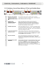
4 Analogue Outputs 1A,
1B, 2A and 2B
Electronically balanced XLR audio output plugs
Pinouts: Pin 1 Screen
Pin 2 Hot
Pin 3 Return
5 Digital Outputs 1 and 2 Digital AES/EBU output for channels 1A/1B and 2A/2B.
AES/EBU is 110 Ohms.
6 Word clock Input A word clock input is provided for synchronisation purposes.
7 Contact Closure (RELAY)
interface
This allows a simple contact closure to recall memories on
the unit. Pin connections are as follows:
Pin 1 - recall Preset / User 1 on Section 1 (the left-hand unit)
Pin 2 - recall Preset / User 2 on Section 1 (the left-hand unit)
Pin 3 - recall Preset / User 3 on Section 1 (the left-hand unit)
Pin 4 - recall Preset / User 4 on Section 1 (the left-hand unit)
Pin 5 - recall Preset / User 1 on Section 2 (the right-hand unit)
Pin 6 - recall Preset / User 2 on Section 2 (the right-hand unit)
Pin 7 - recall Preset / User 3 on Section 2 (the right-hand unit)
Pin 8 - recall Preset / User 4 on Section 2 (the right-hand unit)
Pin 9 - common
Momentarily connect pin 9 to the appropriate other pin (1-8)
to perform a recall.
2 7 3 3 3 3 4 4 4 4 5 5 6