


Controls, Connectors, Indicators: DN9344E
46
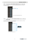
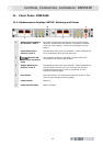
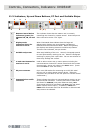
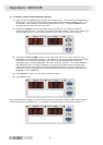
11.2. Indicators, Up and Down Buttons, PC Port and Scribble Strips.
1 Remote Control Active
indicators (green) for
Channel 1A, 1B, 2A and
2B.
This indicator shows that the master unit is currently
controlling this channel by remote control. Green lamps are
often referred to as the “me” lights.
2 Display mode
indicators (blue) for
sections 1 and 2.
When illuminated these indicate that the large red
alphanumeric displays are now showing Last Memory
Recalled and Communications Mode. When extinguished,
the displays are showing electronic scribble-strip names.
There are two indicators, one per section.
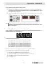
3 Scribble-strip areas Allow easy labelling of the unit. Use only chinagraph pencils
to avoid permanently marking the unit. Remove chinagraph
markings by wiping with a soft cloth. Do not use solvents as
these may damage the surface.
4
UP and DOWN buttons for
sections 1 and 2.
Used to select various set up menu options including the
communications channel for remote control and also contact
closure mode. Active only when in the SETUP menu. (Press
and hold SETUP to enter this menu).
5 PC port connector 8-pin mini-DIN socket for connecting to an RS-232 serial
port on a PC or other remote control device. (Ethercon
connectors are provided on the rear panel for remote control
via Ethernet.)
6 Communictions traffic
indicators
These indicate when there is communications activity on any
of the external interfaces. Transmit and receive data LEDs
are shown for NETWORK (rear panel Ethernet data), DATA
(front panel RS-232 PC port data) and RELAY (the rear panel
RELAY contact closure input). In addition, IP ADDR and
SUBNET LEDs illuminate when the IP Address or Subnet mask
setup menus are selected.
5
1 1 1 1
4 6 4 3 3 3
2
2