


Quick Reference
4
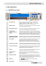
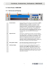
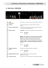
1.2. DN9344E Front Panel
1 Remote control active
indicators (green) x 4
These show that that the master unit is currently controlling
the channel by remote control. Often referred to as the
“me” light. There is one indicator for each of the channels
1A, 1B, 2A and 2B.
2 Alphanumeric displays
for sections 1 and 2
Each section has two large, red, three-digit alphanumeric
displays that show electronic scribble-strip information, Last
Memory Recalled and Communications Mode, or Set Up
menu options.
3 Display mode
indicators (blue) for
sections 1 and 2
Each section has a blue indicator that illuminates to show
that the large, red alphanumeric displays are showing Last
Memory Recalled and Communications Mode. When
extinguished, the displays are showing electronic
scribble-strip names.
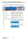
4 Scribble Strips for
sections 1 and 2
Scribble-strip areas allow easy labelling of the unit. Use
only chinagraph pencils to avoid permanently marking the
unit. Remove chinagraph markings by wiping with a soft
cloth. Do not use solvents as these may damage the
surface.
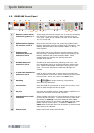
5
UP and DOWN buttons for
sections 1 and 2
Used to select various set up menu options including the
communications channel for remote control and also contact
closure mode. Active only when in the SETUP menu.
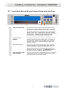
6 Metering
Input,
and Output metering incorporating
multi-point clip indication.
7
SETUP button
Press and hold for one second to access Set Up menu, then
press to step through the Set Up pages.
8 PC port Use with the supplied cable to install software updates or to
control the unit from an external computer.
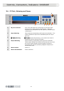
9 Communictions traffic
indicators
These indicate when there is communications activity on any
of the external interfaces. Transmit and receive data LEDs
are shown for NETWORK (rear panel Ethernet data), DATA
(front panel RS-232 PC port data) and RELAY (the rear panel
RELAY contact closure input). In addition, IP ADDR and
SUBNET LEDs illuminate when the IP Address or Subnet mask
setup menus are selected.
10 Power panel Power switch and power ON indication.
3 8 6 10
1 1 1 1
2
2
5 7
3 6 9
5
4 4