


Application Notes
57
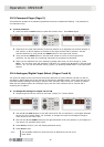
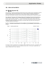
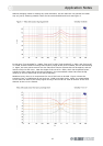
Without changing modes or making any other selections, we can make the unit operate ‘the other
way up’ just by selecting suitable values for the two thresholds and levels see Figure 3.
In this case, [low threshold] is -20dBu, [low level] is 0dB, [high threshold] is -5dBu, and [high level]
is +12dB, so that instead of cutting this frequency range as the level increases, we are now boosting
it. Again, we have precise control over the maximum amount of boost that will be applied, and the
level at which this will occur. Note the shape of the curve for -5dBu, which has ‘expected values’
outside the filter range and at the centre frequency, but intermediate values that show the EQ
ramping in and out either side of the centre frequency.
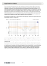
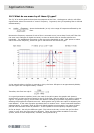
Needless to say, there is no requirement for one of the levels to be 0dB. Figure 4 shows the
transition from a +12dB boost at low level to a -12dB cut at high levels. Again, the intermediate
curves show the effect of the sweep signal moving in and out of the ‘area of interest’ of the level
detector as the curve is formed.