


12
3
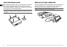
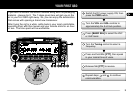
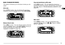
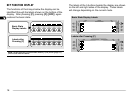
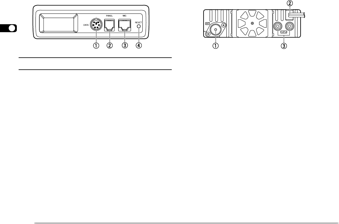
MAIN UNIT — FRONT
Note: Turn the transceiver power OFF before connecting or removing
cables.
qq
qq
q DATA connector
Accepts a 6-pin mini DIN plug for connecting to an
external TNC {page 71}.
ww
ww
w PANEL connector
Insert the 6-pin plug of the supplied modular plug
cable for connecting the front panel {page 4}.
ee
ee
e MIC connector
Insert the modular plug on the microphone cable until
the locking tab clicks {page 8}.
rr
rr
r RESET button
Press for 1 second or longer to perform Full Reset
{page 39}. No confirmation message appears. Use
this switch when the microcomputer and/or the
memory chip malfunction due to ambient factors.
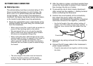
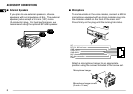
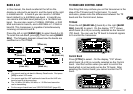
MAIN UNIT — REAR
qq
qq
q Antenna connector
Connect an external antenna {page 7}. When making
test transmissions, connect a dummy load in place of
the antenna. The antenna system or load should
have an impedance of 50 Ω. The TM-V708 accepts a
male PL-259 connector. This transceiver has only
one antenna connector because of a built-in duplexer.
ww
ww
w Power Input 13.8 V DC cable
Connect a 13.8 V DC power source. Use the
supplied DC power cable {pages 5 and 6}.
ee
ee
e Speaker jacks
If you wish, connect an optional external speaker for
clearer audio. These jacks accept a 3.5 mm (1/8")
mono (2-conductor) plug. See page 8.