


TMS320C6202
FIXED-POINT DIGITAL SIGNAL PROCESSOR
SPRS072B – AUGUST 1998 – REVISED AUGUST 1999
69
POST OFFICE BOX 1443 • HOUSTON, TEXAS 77251–1443
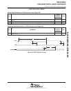
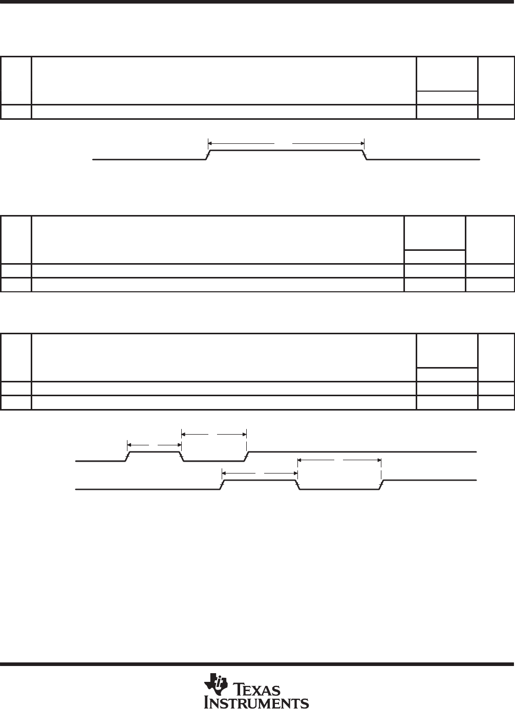
DMAC, TIMER, POWER-DOWN TIMING
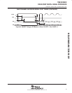
switching characteristics for DMAC outputs
†
(see Figure 46)
NO. PARAMETER
’C6202-200
’C6202-233
’C6202-250
UNIT
MIN MAX
1 t
w(DMACH)
Pulse duration, DMAC high 2P–3 ns
†
P = 1/CPU clock frequency in ns. For example, when running parts at 250 MHz, use P = 4 ns.
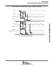
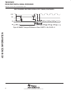
DMAC[3:0]
1
Figure 46. DMAC Timing
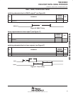
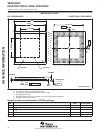
timing requirements for timer inputs
†
(see Figure 47)
NO.
’C6202-200
’C6202-233
’C6202-250
UNIT
MIN MAX
1 t
w(TINPH)
Pulse duration, TINP high 2P ns
2 t
w(TINPL)
Pulse duration, TINP low 2P ns
†
P = 1/CPU clock frequency in ns. For example, when running parts at 250 MHz, use P = 4 ns.
switching characteristics for timer outputs
†
(see Figure 47)
NO. PARAMETER
’C6202-200
’C6202-233
’C6202-250
UNIT
MIN MAX
3 t
w(TOUTH)
Pulse duration, TOUT high 2P–3 ns
4 t
w(TOUTL)
Pulse duration, TOUT low 2P–3 ns
†
P = 1/CPU clock frequency in ns. For example, when running parts at 250 MHz, use P = 4 ns.
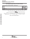
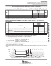
TINPx
TOUTx
4
3
2
1
Figure 47. Timer Timing
ADVANCE INFORMATION