


TMS320C6202
FIXED-POINT DIGITAL SIGNAL PROCESSOR
SPRS072B – AUGUST 1998 – REVISED AUGUST 1999
44
POST OFFICE BOX 1443 • HOUSTON, TEXAS 77251–1443
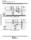
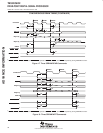
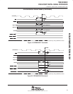
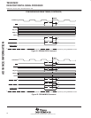
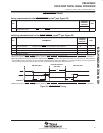
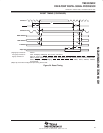
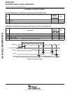
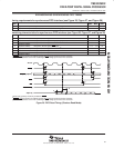
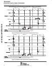
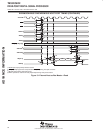
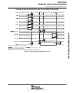
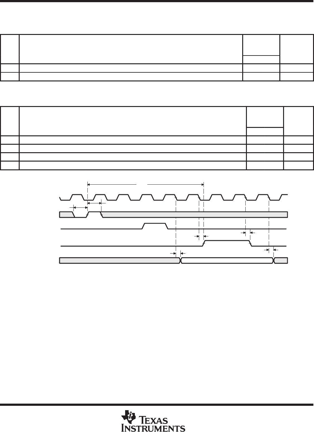
EXTERNAL INTERRUPT TIMING
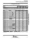
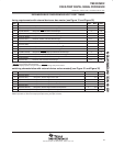
timing requirements for interrupt response cycles
†
(see Figure 25)
NO.
’C6202-200
’C6202-233
’C6202-250
UNIT
MIN MAX
2 t
w(ILOW)
Width of the interrupt pulse low 2P ns
3 t
w(IHIGH)
Width of the interrupt pulse high 2P ns
†
P = 1/CPU clock frequency in ns. For example, when running parts at 250 MHz, use P = 4 ns.
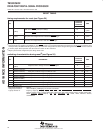
switching characteristics during interrupt response cycles
†
(see Figure 25)
NO. PARAMETER
’C6202-200
’C6202-233
’C6202-250
UNIT
MIN MAX
1 t
R(EINTH
–
IACKH)
Response time, EXT_INTx high to IACK high 9P ns
4 t
d(CKO2L-IACKV)
Delay time, CLKOUT2 low to IACK valid 0 10 ns
5 t
d(CKO2L-INUMV)
Delay time, CLKOUT2 low to INUMx valid 0 10 ns
6 t
d(CKO2L-INUMIV)
Delay time, CLKOUT2 low to INUMx invalid 0 10 ns
†
P = 1/CPU clock frequency in ns. For example, when running parts at 250 MHz, use P = 4 ns.
Interrupt Number
6
5
4
4
3
2
CLKOUT2
EXT_INTx, NMI
1
Intr Flag
IACK
INUMx
Figure 25. Interrupt Timing
ADVANCE INFORMATION