


Installation
Runco X-200i Series Installation/Operation Manual 25
PRE
L
IMINAR
Y
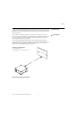
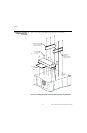
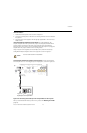
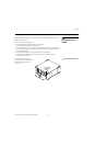
Install Lens Motor:
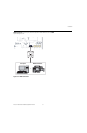
1. Position the AutoScope lens motor as shown in Figure 3-7.
2. Line up the mounting holes on the lens motor housing with those on the underside of
the projector.
3. Secure the motor to the projector with the eight (8) supplied M6 x 12mm Pan-Head
Phillips screws.
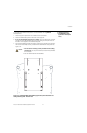
Install Ceiling Mount Adapters/Projector Stands: For ceiling installations, the
adapters bring the attachment points for the projector mounting rails (included with the
projector ceiling mount kit) from the bottom of the projector above and behind the
AutoScope lens motor housing. For floor installations (where the projector is upright), the
adapters allow the projector to lie flat on the mounting surface.
Using six (6) each of the supplied, Pan-Head Phillips screws, attach the AutoScope
Ceiling Mount Adapters/Projector Stands to the projector as shown in
Figure 3-7.
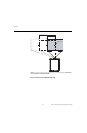
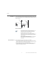
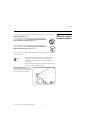
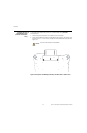
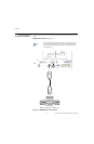
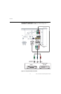
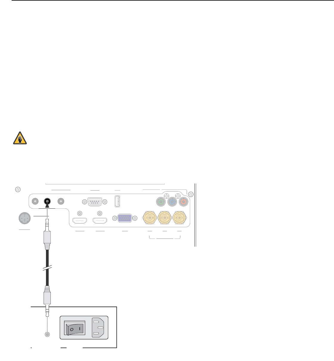
Connecting the AutoScope Lens Motor to the Projector: Connect the AutoScope
lens transport motor to a 12-volt trigger output on the projector, as shown in Figure 3-8.
Figure 3-8. Connecting the AutoScope Lens Transport Motor to the Projector
After you have installed the AutoScope lens motor, proceed with Mounting the X-200i
(page 28).
DO NOT OVER-TIGHTEN THE SCREWS.
Caution
3D SYNC
3D SYNC
RS-232
RS-232
USB
USB
COMPONENT 1
COMPONENT 1
12V TRIGGER
III
12V TRIGGER
WIRED REMOTE
WIRED REMOTE
HDMI 2
HDMI 2
RGB
RGB
Y
Y
Pb
Pb
Pr
Pr
HDMI 1
HDMI 1
COMPONENT 2
COMPONENT 2
3
D
S
YN
C
3
D
S
YN
C
R
S
-2
3
2
R
S
-2
32
USB
U
S
B
CO
MP
O
NEN
T
1
CO
MP
O
NEN
T
1
WIRED REM
O
T
E
WIRED REM
O
T
E
HDMI
2
HDMI
2
R
G
B
R
GB
Y
Y
Pb
P
b
Pr
Pr
HDMI
1
H
DMI
1
COMPONENT
2
CO
MP
O
NEN
T
2
AuptoScope Lens Transport Motor
AC Input
+12V
Trigger Input
Power
Switch
3.5-mm
mini plug