


External Control
92 Runco X-200i Series Installation/Operation Manual
PRE
L
IMINAR
Y
6.2
Using Discrete IR
Codes
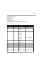
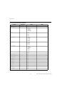
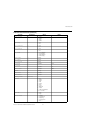
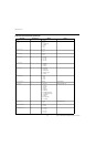
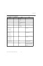
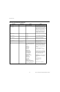
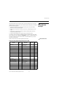
The X-200i accepts commands in the form of IR signals that conform to the NEC protocol.
Each X-200i remote control button has an NEC control code associated with it.
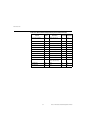
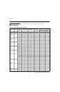
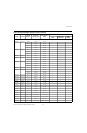
As shown in Table 6-1, there are two complete sets of remote codes (designated “Set 1”
and “Set 2”). Through the on-screen menu, the projector can be configured to use either
set. The reason for two sets is to allow control of more than one product in the same
room without interference. The remote control can also be configured to use either code
set (refer to
Infrared Remote on page 71).
You can use these codes to program a third-party, “universal” remote control unit to work
with the X-200i. These third-party products usually come with a computer software
application for this purpose. For more information, consult the documentation provided
with the remote control unit.
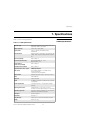
IR Command Protocol The IR control codes have the following characteristics:
• Each code consists of the following:
•A leader pulse (a modulated pulse of 9 ms followed by a non-modulated pulse of
4.5 ms);
•16 address bits - 0x06 0xF9 (binary 00000110 11111001);
•16 data bits: eight (8) bits for the command followed by the logical inverse of the
command; and
•An end pulse (a modulated pulse of 0.56 ms, similar to the modulated pulse in the
‘0’ and ‘1’ bits).The end of the modulated pulse constitutes the end of the data
transmission.
• The carrier frequency is 38 kHz, with the modulated pulses having a 33% duty cycle.
• Commands are sent at a maximum rate of 9 Hz.
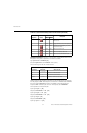
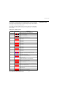
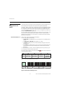
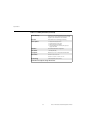
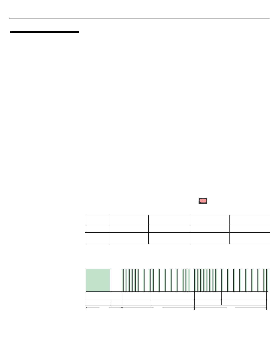
For example, here is the NEC control code for the ON ( ) button on the X-200i remote
control unit (using Code Set 1):
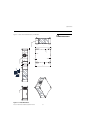
Figure 6-1 shows the pulse train for this command.
Figure 6-1. NEC Protocol Message Format
➤
Hex 06 F9 01 FE
Binary 00000110 11111001 00000001 11111110
Function Address Byte 1 Address Byte 2 Command
Command
(Logical Inverse)
9 ms
13.5 ms 27 ms
27 ms
Address Byte 1Leader Pulse Address Byte 2 Command Byte Command Byte (logical inverse)
000001 1 0
1 1 1 1 1 001 00000001 1 1 1 1 1 1 1 0
4.5 ms
End Pulse