


Controls and Functions
Runco X-200i Series Installation/Operation Manual 7
PRE
L
IMINAR
Y
2.2
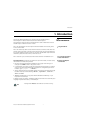
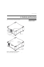
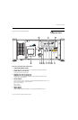
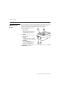
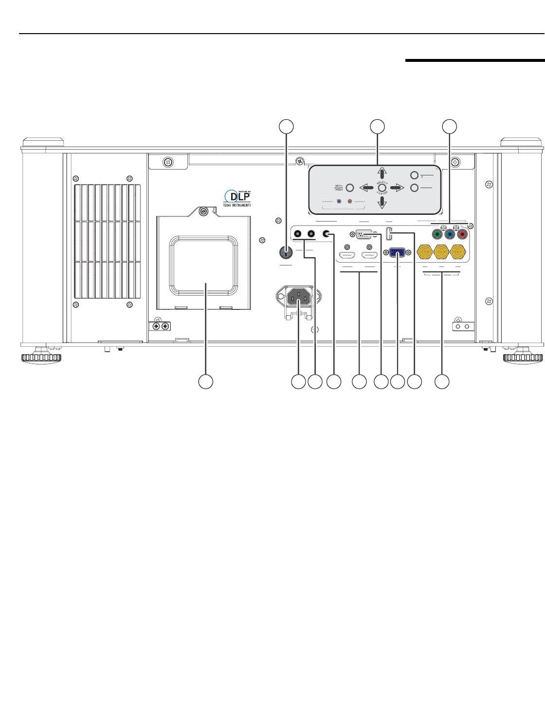
X-200i Rear Panel
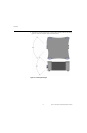
Figure 2-2 shows the X-200i rear panel.
Figure 2-2. X-200i Rear View (without Door)
1. LAMP COMPARTMENT COVER
Remove this cover to access the lamp compartment when replacing the lamp.
2. POWER INPUT (100 to 240 VAC)
Connect the X-200i to power here.
3. TRIGGER 1 (3.5-mm, mini phono jack)
TRIGGER 2 (3.5-mm, mini phono jack)
Provide 12 (+/- 1.5) volt switched output for screen relays with 250mA current
capacity and short protection.
4. WIRED REMOTE
Wired input from a Niles- or Xantech-compatible, infrared (IR) repeater system. It is a
3.5-mm, mini phono jack, wired as follows:
Ring = No connection
Tip = IR Input
Sleeve = Ground
5. HDMI 1 (Digital)
HDMI 2 (Digital)
HDCP-compliant digital video inputs for connecting an HDMI or DVI source.
3D SYNC
3D SYNC
RS-232
RS-232
USB
USB
COMPONENT 1
COMPONENT
12V TRIGGER
III
12V TRIGGER
WIRED REMOTE
WIRED REMOTE
HDMI 2
HDMI 2
RGB
RGB
Y
Y
Pb
Pb
Pr
Pr
HDMI 1
HDMI
COMPONENT 2
COMPONENT 2
POWER
SOURCE
SOURC
POWER
ISSUE
ISSUE
POWER
POWER
LED STATUS
LED STATUS
1
10
2 5 7 86
11
43 9
POWE
R
SO
UR
C
E
SOUR
C
P
O
WE
R
ISSU
E
ISSUE
PO
WER
P
O
WE
R
LED ST
A
T
T
TUS
A
A
LED ST
A
TT
TUS
A
A
12